- ページ 6
スイッチ AMERITRON ARI-500のPDF 取扱説明書をオンラインで閲覧またはダウンロードできます。AMERITRON ARI-500 13 ページ。 Automatic band switch for the ameritron als-500m; ameritron als-600 amplifiers
AMERITRON ARI-500 にも: 取扱説明書 (16 ページ)

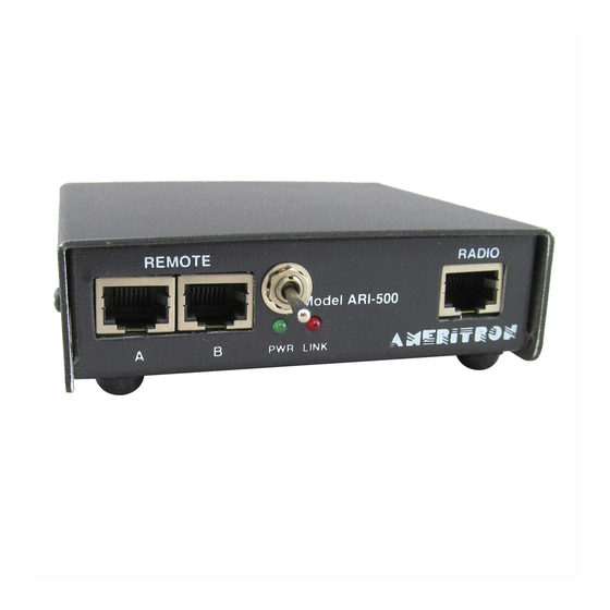
ARI-500 Automatic Band Switch for ALS-500/600
The Yaesu FT-450/950 transceivers provide Band Data, ALC, and AMP Keying from a 10-pin MiniDIN connector on the back of
these radios. These connectors are very difficult to find, therefore it is best to purchase the Yaesu CT-118 Band Data cable (~ $40
from most suppliers), and then construct the cable below to interface from the CT-118 to the ARI-500.
TX GND
1
2
3
9
10
DB15-S
Solder-cup View
Interfacing to the Elecraft K3 Transceiver
The Elecraft K3 outputs band information using the standard 4-line BCD format. Since about SN2370, all K3 radios have pull-up
resistors on the K3 Band Data lines (required). Check the K3 modification page at
K3 radios.
AMP KEY OUT
K3 Accessory Connector
5
4
3
10
9
15
14
13
Interfacing to Kenwood Radios
The Computer port (CAT) is used to retrieve the frequency of the radio. When the ARI-500 is first turned on, the "Auto Information"
(AI) command is sent to the radio. This command causes the Kenwood radio to output the state of the radio (frequency, mode, etc)
anytime the state has changes. The ARI-500 then uses the frequency to determine the appropriate band and then selects the correct
antenna. The diagram below shows how to connect a Kenwood radio with a DB-9M COM port to the ARI-500. Note that pins 7 and
8 (RTS, CTS) on the Kenwood port must be connected together. This ensures that the Kenwood will send the status information to
the ARI-500. There is one second delay from when the status of the radio changes until it is sent out over the serial connection. The
Remote port on the back of Kenwood radios has the amp-key line needed for the ARI-500, and the ALC input from the amplifier if
you wish to use it. Refer to the Kenwood manuals and turn on the amplifier keying relay and set the BAUD rate to 9600.
6
Band A
Band B
Band C
Band D
4
5
6
7
8
11
12
13
14
15
FT-450/950
(Intfc to CT-118)
GND
2
1
Band1
8
7
6
Band2
12
11
HD15-S
Solder-cup View
Band0
Band3
K3 Interface
Connection
Band Data A
Band Data B
Band Data C
Band Data D
Amp Key / TX GND
Ground
Instruction Manual
1 2 3 4 5 6 7 8
GND
Radio Input
1 2 3 4 5 6 7 8
ARI-500 Radio Input
Pin 7
Pin 6
Pin 5
Pin 4
Pin 2
Pin 1
www.elecraft.com
for the modification for earlier
K3 Accessory
Socket
Pin 13
Pin 3
Pin 9
Pin 14
Pin 10
Pin 5
