- ページ 10
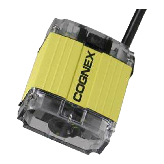
バーコードリーダー Cognex DataMan 100のPDF クイック・リファレンス・マニュアルをオンラインで閲覧またはダウンロードできます。Cognex DataMan 100 18 ページ。 Shd/c-mount kit removal instructions
Cognex DataMan 100 にも: 取り外し方法 (2 ページ), クイック・リファレンス (16 ページ)

- 1. Getting Started
- 2. Setting up Your Dataman
- 3. Reference Information
- 4. Troubleshooting
- 5. Universal Mounting Bracket
- 6. Usb Connections
- 7. Output Wiring Example
- 8. Input Wiring Example
- 9. Training and Trigger Modes
- 10. Results Display
- 11. System Settings
- 12. Digital Output Wiring
- 13. Digital Input Wiring
- 14. Warnings and Notices
Wiring DataMan 100
COGNEX
24VDC
— +
1
1
Power: 5–24 VDC, 2.5W peak. Connect either ground pin to chassis
ground.
Discrete Output: Current sink only; must connect logical ground to
2
common. Outputs are opto-isolated and protected against reverse
polarity. Max current 50 mA @ 24 VDC. Output 1 used for external
illumination control by default.
3
Trigger Input: Opto-isolated, polarity-independent, current source
or sink. Input 0 is dedicated trigger line; Input 1 is not used.
4
RS-232 and USB: If USB connection is detected, USB
communications is automatically selected; otherwise RS-232
connection is used.
DM100 IOBOX
IOB10 200-3001-R1R
DO NOT HOT PLUG
OUTPUT
INPUT
RS232
USB
0
1 C
0
1 C
2
3
4
Output Wiring Example
Input Wiring Example
–
24V
DC
+
–
24V
DC
+
