- ページ 2
コントロールユニット AMES 672GD-19のPDF インストレーション、オペレーション、メンテナンスマニュアルをオンラインで閲覧またはダウンロードできます。AMES 672GD-19 12 ページ。

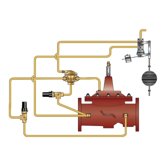
972GD-19 (Globe) On-Off Float Control Valve (6" and Larger)
Standard Components
1 – Main Valve (905GD – Single Chamber)
2 – On-Off Float Control
3A – High Level Adjustment Stop
3B – Low Level Adjustment Stop
4 – Model 22-1 Accelerator Control
5 – Adjustable Closing Speed
6 – Adjustable Opening Speed
X – Isolation Cocks
Operation
The On-Off Float Control Valve is designed to open fully or close
drip-tight as commanded by the Float Control Pilot. The Float Pilot
may be either valve or remote mounted. The valve closes drip tight
when water level reaches the adjustable high-level setpoint, and
opens fully when water level is below the adjustable low-level set-
point, allowing a calculated "draw-down" of water level to increase
tank circulation.
The On-Off Float Pilot directs upstream pressure into and out of the
cover chamber of the 3-way Accelerator Pilot. When the cover of
the Accelerator Pilot is pressurized, the main valve cover chamber
is vented downstream, causing the valve to open fully. When the
cover of the Accelerator Pilot is de-pressurized, the main valve cov-
er chamber is connected to upstream pressure, causing the valve
to close drip tight. Valve opening and closing speeds are separate-
ly adjustable. When water level reaches the adjustable high-level
setpoint, the Float Pilot de-pressurizes the cover chamber of the
Installation
Start-up of an automatic control valve requires that proper procedures be followed. Time must be allowed for the valve to react to
adjustments and the system to stabilize. The objective is to bring the valve into service in a controlled manner to protect the system
from damaging over-pressure.
1.
Prior to installation, flush line to remove debris.
2.
Install valve so the flow arrow matches flow through the line, and gauges to monitor valve inlet and outlet pressures. A Position
Indicator can be installed to provide visual indication of valve position and operation without disassembly.
3.
Install isolation valves upstream and downstream of the main valve.
4.
Provide adequate clearance for valve servicing and maintenance. Refer to valve servicing dimensions on next page. Avoid installing
valves 6" and larger in the vertical position (main valve stem horizontal). Automatic Control Valves (ACVs) are designed for horizon-
tal in-line installation, with the cover facing up (main valve stem vertical). Slow operation or premature stem and guide wear may
occur if valve is not installed according to factory recommendations. Consult factory for detailed engineering review prior to order-
ing if valve is to be installed other than horizontally in-line.
5.
If valve is equipped with a pilot control system, extra precautions should be made during installation to protect the piping circuit
from damage. Only remove the pilot control system from the valve if necessary. Tubing and fittings should be kept clean and
replaced exactly as removed. Consult appropriate hydraulic schematic to ensure proper re-assembly.
6.
Install float control onto tank and connect lines to valve per Watts Model F10-13 Specification Sheet.
7.
Adjust level stops to the high- and low-level settings.
2
IOM-A-ACV-972-19_672-19 2115
5
6
3-Way Accelerator, closing the valve drip tight. The valve remains
closed as water level decreases. When water level reaches the
adjustable low-level setpoint, the Float Pilot pressurizes the cover
chamber of the 3-Way Accelerator, opening the valve fully. High
and low levels are separately adjustable by positioning stop collars
on the float rod(s) at desired opening and closing setpoints.
If desired, the float on-off action of the valve can be "reversed" by
modifying the hydraulic connections of the On-Off Float Pilot.
EDP# 1917110
2
P/L
4
X
X
X
Y/FC
1
FLOW
CLOSES VALVE
OPENS VALVE
© 2021 Watts
3A
3B
