- ページ 8
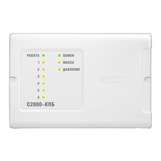
コントロールユニット bolid S2000-KPBのPDF 取扱説明書をオンラインで閲覧またはダウンロードできます。bolid S2000-KPB 17 ページ。 Executive module
bolid S2000-KPB にも: 取扱説明書 (14 ページ)
The unit monitors the total operating current of all the monitored circuits. If the total operating
current has exceeded the maximum permitted value (6 Amperes) the unit generates an Overcurrent
message and shuts off one-by-one the outputs with the maximum operating current. As soon as the
total current doesn't exceed the maximum permitted value the unit generates a Power Restored
message.
1.2 3. Power Inputs
While operating, the unit monitors the voltage at its power inputs U
voltage has dropped at any input (if Both Power Inputs Monitoring is set on) or at both inputs (Both
Power Inputs Monitoring is set off) down to 10 V and lower the unit sends a Power Failure message
over the RS-485 interface.
When the power voltage has been restored for both inputs (if Both Power Inputs Monitoring is set
on) or for any input (if Both Power Inputs Monitoring is set off) up to 11 V and higher, the unit
transmits a Power Restored message over the RS-485 interface.
Power input conditions are indicated by READY LED as shown in the table below:
Power Voltage
1. OK for both inputs
2. Below the normal range for an input
3. Below the normal range for both inputs
The internal circuits of the unit and output circuits are supplied with power by a power input with a
higher voltage.
The values of the current consumed in various conditions are shown in the table below:
All outputs are switched off and OK.
All inputs are in open circuit conditions.
All outputs are switched off and in open circuit conditions.
All inputs are in open circuit conditions.
All outputs are switched off and in short circuit conditions.
All inputs are in short circuit conditions.
One output is switched on and in open circuit conditions,
Other outputs are switched off and OK.
All inputs are in short circuit conditions.
All outputs are switched on and in open circuit conditions.
All inputs are in short circuit conditions.
2.2
Device Failed Mode
The unit proceeds to the Device Failed mode when a fatal error has occurred on calculating the
checksum of the program memory of the built-in microprocessor.
In the Device Failed mode READY and COM LEDs flash alternately while other indicators change
color from green to amber synchronously.
8
Both Power Inputs
Conditions
main
Table 6. Indication of Operation Modes of the Unit
Monitoring
On
Off
On
On for 0.25 s and off for 1.75 s
Off
On
On for 0.25 s and off for 1.75 s
Off
On for 0.25 s and off for 1.75 s
Power
Voltage
12
24
12
24
12
24
12
24
12
24
and U
. When the power
back
READY LED Performance
Lit steady
Lit steady
Lit steady
Table 7. Consumed Current
Max Consumed
Current
35 mA
30 mA
40 mA
35 mA
45 mA
40 mA
75 mA
55 mA
100 mA
75 mA