- ページ 11
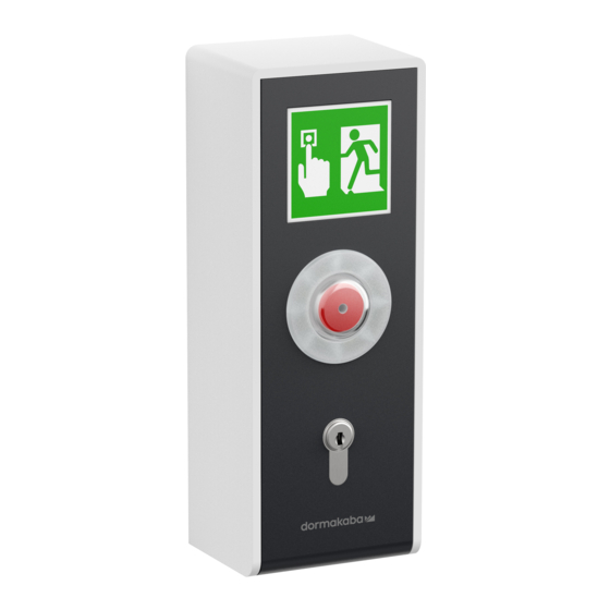
インターホン・システム Dormakaba SafeRoute STL-G SeriesのPDF 取付方法をオンラインで閲覧またはダウンロードできます。Dormakaba SafeRoute STL-G Series 12 ページ。

dormakaba Mounting instructions
4.2
Assignment of terminals and switch/button
LED SLI
X1
X2
24 V DC
1
DCW® bus
A
DCW® bus
B
GND
3
24 V DC
1G
Output 2
Out2
X3
5–28 V DC
In1
GND
3
1
Output 1
Out1
AS
X4
GND
3
TxD
Rx
RxD
Tx
X5
LED SLI
S2
B
S
S4
S5
A
B
S6
STL-G/STL-G NT
DCW
1 A B 3 1G
X2
X1
Connection to key switch ST
Stabilized power supply
Switched voltage (test "Power Reserve Modul M-SVP/SVP")
Common alarm (default value)
Static control (default value)
Output
Locked (default value) Alarm system, e.g. fire alarm system or smoke
detector (see default value)
18k
RS232 interface
Connection to distributor STL-G-S
LED display license card/application card
Service switch for suppression of tamper alarm:
B = Operation (housing tampering contact activated)
S = Service (housing tampering contact shut off, internal and external
tampering messages are suppressed)
Service button
Alarm system switch
A = alarm system activated
B = alarm system not connected (default value)
DIP switch for setting the number of doors (operation of SCU-TL with
license card and multi-door application) or to set up the DCW® address
of other connected emergency buttons (operation of SCU-TL without
license card):
Number of doors
1
2
3
4
WN 059727-45532
®
In1
3
1
X3
Out1
AS
GND
X4
Rx
Tx
X5
DIP switch
0
0
1
0
0
1
1
1
S6
ON
S
S2
B
A
S5
B
S4
DCW® address
DIP switch
1
0
2
1
3
0
4
1
2020-07
Mounting
0
0
1
1
11
