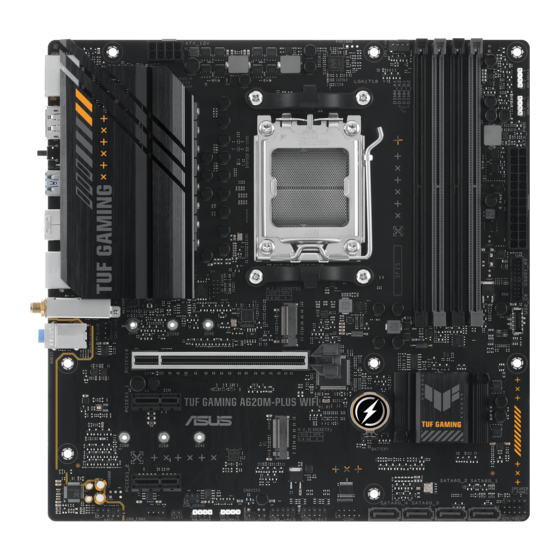
- ページ 16
マザーボード Asus TUF GAMING A620M-PLUS WIFIのPDF マニュアルをオンラインで閲覧またはダウンロードできます。Asus TUF GAMING A620M-PLUS WIFI 38 ページ。
Asus TUF GAMING A620M-PLUS WIFI にも: クイック・スタート・マニュアル (2 ページ), クイック・スタート・マニュアル (2 ページ)

16. S/PDIF Out header
The S/PDIF Out header allows you to connect the Sony/Philips Digital
Interface (S/PDIF) Out module.
The S/PDIF module is purchased separately.
17. Speaker header
The Speaker header allows you to connect the chassis-mounted system
warning speaker. The speaker allows you to hear system beeps and warnings.
18. System Panel header
The System Panel header supports several chassis-mounted functions.
•
System Power LED header (+PWR_LED-)
The 2-pin header allows you to connect the System Power LED. The
System Power LED lights up when the system is connected to a power
source, or when you turn on the system power, and blinks when the
system is in sleep mode.
•
Storage Device Activity LED header (+HDD_LED-)
The 2-pin header allows you to connect the Storage Device Activity LED.
The Storage Device Activity LED lights up or blinks when data is read
from or written to the storage device or storage device add-on card.
•
Power Button/Soft-off Button header (PWR_BTN)
The 2-pin header allows you to connect the system power button. Press the power
button to power up the system, or put the system into sleep or soft-off mode
(depending on the operating system settings).
•
Reset button header (RESET)
The 2-pin header allows you to connect the chassis-mounted reset button. Press the
reset button to reboot the system.
19. BIOS FlashBack
The BIOS FlashBack™ LED lights up or blinks to indicate the status of
the BIOS FlashBack™.
Scan the QR code for more information on BIOS FlashBack
function.
1-6
LED
TM
D+
TX1-
D-
GND
GND
RX1+
RX2-
RX1-
RX2+
VBUS
GND
CC1
TX2-
NC
TX2+
NC
VBUS
SPDIF_OUT
PIN 1
SPEAKER
PIN 1
F_PANEL
+PWR_LED-
PIN 1
+HDD_LED-
TM
Chapter 1: Product Introduction
PWR_BTN
RESET
