- ページ 11
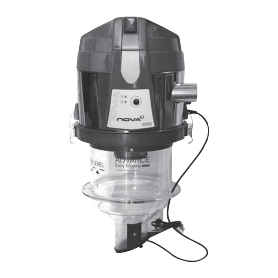
掃除機 Advance acoustic NOVA 3のPDF 組立・使用・メンテナンスマニュアルをオンラインで閲覧またはダウンロードできます。Advance acoustic NOVA 3 20 ページ。

To facilitate these operations, the vacuum unit is supplied with a template for preparing the
holes.
See fi gures 1 to 3.
Where it is not possible to place the dispenser discharge outlet inside the tank, a maximum level
sensor must be installed in the tank, connecting it to the panel which controls the system, to
prevent fuel leaks during the loading cycles.
1
6.3 Warning for installations on controlled pressure tanks
It is important to remind that pneumatic transport systems work modifying the state of pressures
in the different components of the installation itself: in particular, during the functioning of our
systems, the negative pressure inside the dispenser ranges from 0,080 to 0,24 bar (-1,16 to -3,48
psi).
Note: when the system is starting, an air suction from the pellet discharge fl ap placed on the
bottom of the dispenser may occur.
Afterwards, the same may happen during the dispenser fi lling phase, due to small wood particles
snagged between the fuel outlet and the lower closing fl ap, which impede the perfect sealing.
These leakages don't prejudice the system operation, but they could change the negative
pressure inside the boiler tank, with a risk for boiler safety.
Is it possible to fi x the situation mainly by programming the working time of the fuel transfer
system only when:
A) The brazier of the boiler is switched off and cold
B) The loading door of the tank is open
C) The communication channel between the fuel tank and the boiler brazier is completely closed
D) The smoke extraction fan of boiler is working at the max power;
E) On the boiler tank is present an electrical valve, with proper dimensions, connected to the fuel
feeding transport system, which allows an easy compensation of the air sucked.
31/05/2021 Rev:1.0.4
2
3
English
11
