- ページ 2
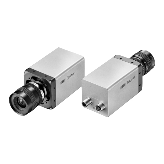
デジタルカメラ Baumer VLXT.IのPDF クイック・スタート・マニュアルをオンラインで閲覧またはダウンロードできます。Baumer VLXT.I 2 ページ。

General Description
1
2
3
4
7
No.
Description
No.
Description
1
Lens mount (C-mount)
5
Ethernet port
2
Lens control (not connected)
6
Camera LED
4 x Tube Adapter /front mount-
3
7
GigE LED
ing threads
4
Power- and process interface
Data Interface / Digital IOs
Ethernet
(SACC-CI-M12FS-8CON-L180-10G)
8
1
7
2
6
3
5
4
1 MX1+
5 MX4+
2 MX1-
6 MX4-
3 MX2+
7 MX3-
4 MX2-
8 MX3+
Power supply / Digital IOs (on camera side)
(SACC-CI-M12MS-12CON-L180)
M12 / 12 pins / wire colors of the connecting cable (ordered separately)
1 Power V
7
OUT3 (Line6)
brown
CC
2 GND (Power)
blue
8
RS232 Txd (Line2)
3 IN1 (Line0)
white
9
OUT4 (Line7)
4 OUT1 (Line4)
green
10 RS232 RxD (Line3)
5 IN2 (Line1)
pink
11 GND (IO)
6 OUT2 (Line5)
yellow
12 Power (IO)
LED Signaling
5
6
LED
1
2
Power Supply
Power V
CC
Caution
In order to achieve the mentioned IP protection level, the M12 connectors
need to be tightened with a torque value of 0.4 Nm.
For that Baumer suggests the use of a torque driver (such as Wiha Tor-
IP
Protection
queVario
actuator cables with M12 connector (such as Phoenix Contact SAC BIT
M12-D15).
black
grey
red
violet
grey-pink
red-blue
1
2
Signal
Meaning
green static
link active
GigE LED
green flash
receiving
yellow static
Camera LED
yellow flash
transmitting
orange static
overheated
Power Supply
24 V ± 20 %
For UL conform installation:
Class 2 per NEC / Protection Class III
The device is intended to be supplied from an isolated Limited
Energy Source per UL61010-1, 3rd ed cl. 9.4 or Limited Power
Source per UL60950-1 or Class 2 per NEC.
-S ESD) in combination with a wrench for assembling sensor/
®
Heat Transmission
Caution
Provide adequate dissipation of heat, to ensure that the temperature
does not exceed the values in the table below.
The surface of the camera may be hot during operation and immediately
after use. Be careful when handling the camera and avoid contact over a
longer period.
As there are numerous possibilities for installation, Baumer do not speci-
fiy a specific method for proper heat dissipation, but suggest the following
principles:
▪ operate the cameras only in mounted condition
▪ mounting in combination with forced convection may provide proper
heat dissipation
T
error
Measure Point
T
Installation
Installation of the camera:
▪ Connect the camera using an appropriate cable (at least Cat-5e) to the GigE
board on your PC.
▪ If required, connect a trigger and / or flash to process interface.
▪ Connect the camera to power supply.
open wire
Installation sample
1 - Cable for trigger and flash
2 - GigE cable
3 - PCI board
Maximal Temperature
+65 °C (149 °F)
