- ページ 6
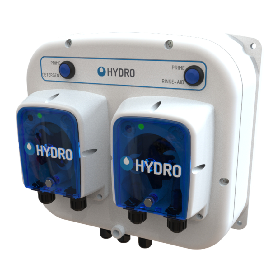
ディスペンサー Dover HYDRO DM-500のPDF ユーザーマニュアルをオンラインで閲覧またはダウンロードできます。Dover HYDRO DM-500 14 ページ。 Warewash dispenser

2.OO installation
2.O1 Site Survey & Installation Requirements
WARNING! This product is intended to be installed by experienced installers, in accordance with all applicable
electrical and plumbing codes.
•
Unit must not be installed near areas that suffer excess temperature changes, direct sunlight, frost or moisture of any kind.
•
Area must be free of high levels of electrical noise.
•
Ensure the unit can be mounted in an accessible position above the height of the required discharge location.
•
Unit must be mounted on a suitable wall, that is flat and perpendicular to the floor.
•
The unit location should be well lit for any maintenance and free of high levels of dust / air particulates.
•
Scheduled maintenance should be carried out on the dispenser at least once per year.
2.O2 Wall Mount
1) Choose an installation location that is:
•
Within 1.5m (4.5 ft.) of the product containers.
•
At a reasonable height above the wash tank on the dish machine that allows for easy maintenance access.
•
Away from any direct sources of steam, water spray, and high temperatures.
•
Close enough to the dish machine electrical control panel to allow dispenser wiring without use of an external junction
box (not provided) wherever possible.
2) Use provided holes in the corners of the DM-500 cabinet as a drilling template in a suitable mounting location.
3) Wall anchors are provided, please ensure they are appropriate to the wall/surface being mounted to.
4) Attach the DM-500 directly to the mounting surface with the hardware provided.
2.O3 Mechanical Installation
Installing the Rinse Injection Fitting
1) Install the rinse injection fitting to conform to local plumbing codes.
2) The injection fitting is designed to fit global needs. It should thread
directly into a 1/8" NPT (North America) or a BSP (Global) female
threaded connection. As an alternative to the threaded connection a
barb fitting adapter is also included.
3) If the machine's rinse plumbing is thin-wall pipe, use a saddle clamp
with the 1/8" threaded hole.
4) If the machine already has a tapped hole to accommodate the fitting,
skip to Step 8
5) Choose a location for the rinse injection fitting that is downstream from
the vacuum breaker and at the proper height per local plumbing codes.
This point is either into the pressurized rinse line or upstream of the
booster heater for the rinse water..
6) To create the threaded connection at your selected location, drill a
9mm (11/32") hole in the rinse plumbing at the injection location.
7) Tap the hole drilled in step 6 with a 1/8" tap (NPT or BSP depending on
the region)
8) Install the injection fitting. Use thread sealant to ensure a leak-free
assembly.
6
Chemical
Pickup
Tubing
Compression
Nut
Check Valve
& Injector
Threaded
Fitting
Rinse Injection
Fitting Threaded
Rinse Injection
Fitting Barbed
Threaded
Barb
