- ページ 8
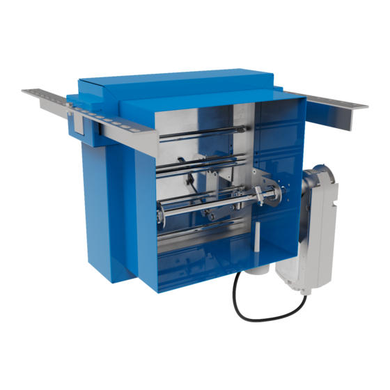
防火・防煙ダンパー Advanced Air 2530のPDF インストレーション、オペレーション、メンテナンスマニュアルをオンラインで閲覧またはダウンロードできます。Advanced Air 2530 16 ページ。 Air control fire & smoke damper

FIRE & SMOKE – 2530 ADJUSTABLE FRAME SYSTEM FOR TWO HOUR RIGID SUPPORTING CONSTRUCTION (SUPPORT TWO SIDES)
M10 drop rods
AFS rail
AFS bracket,
bracket slot,
and Z-piece
Thermal probe
Fire batt
135mm (or thicker) blockwork,
masonry or homogeneous
concrete wall to BS EN 1363-1:2020
2530 W/AFS
PRODUCT
BRE 287810D
CLASSIFICATION REPORT NO.
TESTED INSTALLATION METHOD SHOWN. DIFFERING INSTALLATION METHODS TO THIS MUST BE APPROVED BY THE BUILDING CONTROL AUTHORITY (BCA) BEFORE PROCEEDING.
Preparation
1
Ensure that the damper is kept
in a clean dry environment and
that there is no damage to the
damper.
2
Remove
all
the
before installation.
3
Work out the opening size to be
cut using the adjacent table.
Installation sequence
4
Two M10 drop rods shall be fitted on either side of the drywall. These should be securely installed in
line with the manufacturer's fixing instructions in a position to match the AFS rail.
5
The drop rods should have a nut screwed on for clamping the rail from above.
6
Slide the AFS rails on each side of the damper into the brackets and insert the "Z" piece into the
bracket slot pushing it up against the underside of the rail. Insert the 8mm bolt from above into the slot
through the "Z" piece fitting the nut until tight to secure the rail.
7
The damper should be centrally positioned in the opening with the access side flush with the wall,
as detailed in the drawing. The drop rods are to slide through the slots in the rail and a nut screwed
on to take the support of the damper rail. The damper must then be levelled and when in the correct
position the nut above the rail should be tightened against the rail.
8
The galvanised mild steel ductwork connecting to the damper spigots must overlap by up to 40mm,
leaving a minimum 10mm clearance for any duct expansion in a fire situation.
9
The galvanised mild steel ductwork connections must be sealed with an approved galvanised mild
steel ductwork sealer and fixed with low resistance fixings such as aluminium rivets that will melt at
high temperature allowing the duct to break away without affecting the integrity of the installation.
10
The connecting galvanised mild steel ductwork must be independently supported within one metre of
the connections and have been installed in accordance with DW144.
11
The gap between the damper and the wall opening will need filling with two layers of 50mm thick
140kg/m3 fire batt cut to an interference fit and pushed in to place. All cut edges must be sealed with
a fire batt sealant to BS EN 13501-2. A fire rated intumescent mastic to BS EN 13501-2 shall be applied
to each joint.
12
An access door should be fitted on the access side of the damper to enable the inspection and
maintenance of the damper.
13
When the damper installation has been completed checks should be made to ensure the AFS rails are
secure and there is no movement, operation of the damper should be checked.
14
Complete DW145 Fire Damper Certificate.
RIGID SUPPORTING CONSTRUCTION, SUPPORT TWO SIDES
APPLICATION
E120 (VE I O) S
CLASSIFICATION
Nom. duct size
Width
Opening
min.
200mm x 200mm
Nom. duct
and above
+194mm
Below
394mm
packaging
200mm x 200mm
Circular duct
Nom. duct
over 175mm
+219mm
Circular duct
394mm
under 175mm
Height
Opening
Opening
Opening
max.
min.
max.
Nom. duct.
Nom. duct
Nom. duct
+350mm
+100mm
+350mm
550mm
300mm
550mm
Nom. dia.
Nom. dia.
Nom. dia.
+550mm
+125mm
+375mm
550mm
300mm
550mm
8
