- ページ 9
計測機器 Amprobe PRM-4のPDF ユーザーマニュアルをオンラインで閲覧またはダウンロードできます。Amprobe PRM-4 14 ページ。 Phase sequence and motor rotation tester

correct the problem before returning to the 3-phase rotation test.
Motor Rotation Test
This test can be used to verify the shaft rotation and the M1-M2-M3
connections or to determine the M1-M2-M3 connections on a motor
that is not marked.
�� Warning
Make all connections with circuits unpowered. If the clockwise or
counterclockwise REd indicator is oN before rotating the motor
shaft, voltage is present. Stop measuring. Remove the test leads and
turn off the external power.
1.
Use a multimeter to verify that no voltage is present on the motor
windings.
2.
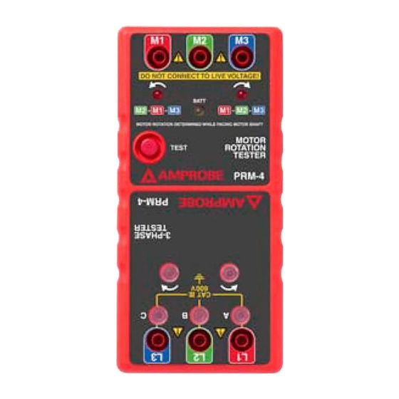
Connect the color coded test leads to the three motor input
terminals M1- M2-M3. Press the power button (See figure 2). The
green indicator light will be on.
3.
facing the motor shaft, hand rotate the motor shaft clockwise.
4.
if the clockwise indicator (
are correct for clockwise rotation.
5.
if the counterclockwise (
connections are correct for counterclockwise rotation.
6.
if the motor rotation direction is wrong, reverse any two of the
M1-M2-M3 connections and repeat the test.
After 3-phase rotation and motor phasing are verified:
1.
Turn off power at the source.
2.
Connect the previously identified power wire l1 to motor wire
M1. Repeat the connections for l2 to M2 and l3 to M3. See figure
3.
3.
inspect the connections for electrical safety.
The motor will rotate in the desired direction when power is
applied.
MAINTENANCE
if the PRM-4 appears to operate incorrectly, check the following
items:
1.
Review the operating instructions to ensure the meter is being
�) is on, the M1-M2-M3 connections
�) indicator is on, the M1-M2-M3
8
