- ページ 5
コントロールユニット AMS AS5247のPDF ユーザーマニュアルをオンラインで閲覧またはダウンロードできます。AMS AS5247 13 ページ。 Usb interface & programming box
AMS AS5247 にも: ユーザーマニュアル (14 ページ)

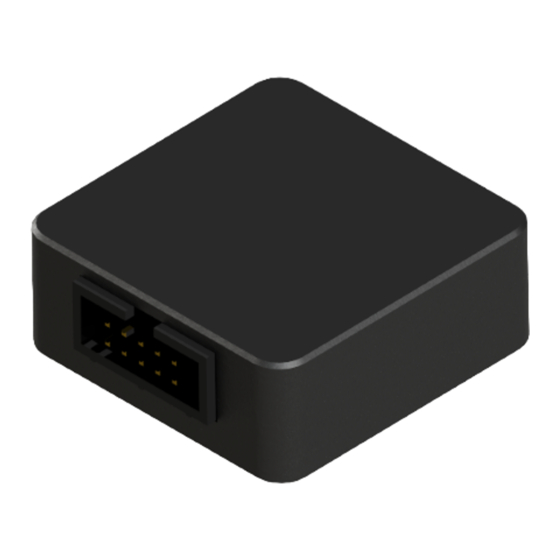
USB I&P Box
User Manual
Product
Description
AS5048B
14-bit Angular Position Sensor with I2C Interface
AS5050A
Low Power 10-Bit Magnetic Position Sensor
AS5055A
Low Power 12-Bit Magnetic Position Sensor
AS5147
14-bit On-Axis Magnetic Rotary Position Sensor
AS5147P
14-bit On-Axis Magnetic Rotary Position Sensor
AS5247
14-bit Dual-Die Magnetic Rotary Position Sensor
AS5510
Linear Hall Sensor with I²C Output
AS5600
12-bit Programmable Contactless Potentiometer
AS5601
12-bit Programmable Contactless Encoder
2.3
Pin-out
The pin-out of the USB I&P box is shown below in
Table 3:
USB I&P Box Pin-out and wire description
Pin #
Color
Definition
1
Brown
5V Supply
2
Red
3.3V Supply
3
Orange
SPI-CS(0)
4
Yellow
I2C-SCL
5
Green
SPI-CLK
6
Blue
I2C-SDA
7
Purple
SPI-MOSI
8
Grey
SPI-CS(1)
9
White
SPI-MISO
10
Black
GND
Note: The interface voltage of the USB I&P Box is 3,3V. Use the 3,3V mode when connecting to a
position sensor board.
3
First steps with the USB I&P Box
The first steps to get started with the USB I&P Box are described below in
www.ams.com
Table 3
SPI Mode
Not used
Positive power supply
SPI-CS(0)
Not used
SPI-CLK
Not used
SPI-MOSI
Optional (dual die version)
SPI-MISO
GND
Revision 1.4 / 09/09/2015
Adapterboard available
yes
yes
yes
yes
yes
yes
yes
yes
yes
Figure
2.
page 5/13
