- ページ 8
アダプター AMS AS5601のPDF 操作マニュアルをオンラインで閲覧またはダウンロードできます。AMS AS5601 12 ページ。 Usb interface & programming box
AMS AS5601 にも: ユーザーマニュアル (13 ページ), マニュアル (13 ページ)

AS5601-SO_RD_ST
Operation Manual
3.2.1 Low Power Mode
Three low power modes are available to reduce the power consumption down to 1,5mA max.
3.2.2 Hysteresis
A 1 to 3 LSB hysteresis of the 12-bit resolution can be enabled.
3.2.3 Output selection
Per default, the Analog Output is active if a magnet is present. Additionally the Output Pin can be
switched to PWM with the option to select a PWM frequency (115Hz,230Hz,460Hz,920Hz)
3.2.4 Slow Filter
The slow filter allows improving the output noise. The default setting for the Slow Filter is 16x and
can be reduced for faster response.
3.2.5 Fast Filter
The fast filter is active by selecting a Fast Filter Threshold. If the output value remains below the
threshold, the output noise is defined by the slow filter setting. When exceeding the threshold, the
output noise is defined from the fast filter for fast output response. The output noise is again defined
by the slow filter as soon as the output stays in the threshold again.
3.2.6 Watchdog
If the watchdog is active, the AS5601 automatically enters Low Power Mode 3 after one minute if
the output value stays within a threshold of 4 LSB.
4
Board Schematics, Layout and BOM
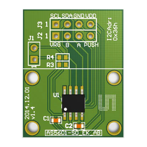
The schematic, layout and BOM of the adapter board are shown below for reference.
4.1 Schematics
The schematic of the board is shown below in
Figure
7.
Figure 7:
Reference Module PCB Schematic
www.ams.com
Revision 1.0 / 30.06.2014
page 8/11
