- ページ 9
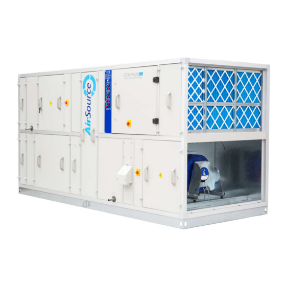
エア・ハンドラー AirSource TempAirのPDF 据付・操作・メンテナンス説明書をオンラインで閲覧またはダウンロードできます。AirSource TempAir 20 ページ。 Air handling units, airsource heatpumps

Electrical Connection
Do not penetrate or obstruct the removal of any doors/access panels
Do not penetrate or obst
cables penetrate the AHU casework, ensure that the casework is
penetrate the AHU casework, ensure that the casework is adequately sealed to
prevent air leakage/water ingress. If the unit is provided with package controls then
prevent air leakage/water ingress. If the unit is provided with package controls then
prevent air leakage/water ingress. If the unit is provided with package controls then
always use the cable entry as provided.
always use the cable en
Ductwork Connection
Ensure ductwork is adequately sealed to the AHU and supported separately.
Ensure ductwork is adequately sealed to the AHU and supported separately. Ductwork
Ensure ductwork is adequately sealed to the AHU and supported separately.
connection is to be of the size as recommended on our general arrangement drawing.
connection is to be of the size as recommended on our general arrangement drawing.
connection is to be of the size as recommended on our general arrangement drawing.
3 Phase Motor Wiring Diagrams
IT IS IMPORTANT TO USE THE CORRECT WIRING DIAGRAM AS DETAILED BELOW
TO SUIT THE INCOMING MAINS VOLTAGE. FAILURE TO DO SO MAY RESULT IN
TO SUIT THE INCOMING MAINS VOLTAGE. FAILURE TO DO SO MAY RESULT IN
TO SUIT THE INCOMING MAINS VOLTAGE. FAILURE TO DO SO MAY RESULT IN
PERMANENT DAMAGE TO THE MOTOR/
PERMANENT DAMAGE TO THE MOTOR/CONTROL GEAR.
STAR Connection (Y):
DELTA Connection (
Inverters
When inverters are provide
When inverters are provided fitted to the AHU the electrical connection from the
inverter to the motor will be completed at the factory, refer to inverter
inverter to the motor will be completed at the factory, refer to inverter
inverter to the motor will be completed at the factory, refer to inverter
documentation for wiring & setup instructions.
documentation for wiring & setup instructions.
Loose inverters may be provided for fitting and wiring by others, refer to inve
Loose inverters may be provided for fitting and wiring by others, refer to inverter
Loose inverters may be provided for fitting and wiring by others, refer to inve
documentation for wiring & setup instructions.
documentation for wiring & setup instructions.
ruct the removal of any doors/access panels. Where electrical
USE THE CORRECT WIRING DIAGRAM AS DETAILED BELOW
USE THE CORRECT WIRING DIAGRAM AS DETAILED BELOW
Δ
):
):
d fitted to the AHU the electrical connection from the
adequately sealed to
Installation, Operation & Maintenance Manual
stallation, Operation & Maintenance Manual
8
