- ページ 5
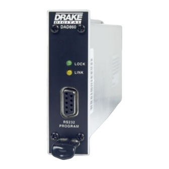
メディア・コンバーター DRAKE DAD860のPDF 取扱説明書をオンラインで閲覧またはダウンロードできます。DRAKE DAD860 15 ページ。 Digital to analog decoder
DRAKE DAD860 にも: 取扱説明書 (15 ページ)

DAD860
DAD860
DAD860 Controller
LOCK
DRAKE
DAD860
LINK
ENTER
UNIT
RS232
RS232
PROGRAM
PROGRAM
GENERAL DESCRIPTION
The R. L. Drake DAD860 is a high quality, low
noise, frequency agile, digital to analog decoder
designed for receiving digital signals from off-air or
CATV channels. Output of the DAD860 is base-
band NTSC video and stereo audio.
The output of the DAD860 can be connected to
VMM600 or VMM860 series modulators to place the
programming on a specific off-air or CATV channel,
or to any other device requiring baseband audio and
video input such as monitors, video recorders, etc.
INSTALLATION AND MOUNTING
Install the DAD860 decoders in the RMM12 rack
mounting frame. Slide each module into the frame
from the front so that the mounting rails on the top
and bottom of the DAD860s engage the mounting
tracks on the frame. Similarly, mount the PSM121
Power Supply, again making sure that its mounting
rails line up with the tracks in the frame. Apply the
same mounting procedure to the DAD860 Controller.
Note that, while the sketches on this page show only
DAD860s installed, any combination of DAD860s and
VMM600 or VMM860 modulators could be installed. If
no controller is used, up to twelve DAD and/or VMM
modules can be installed per RMM12.
Plug the supplied power cable into the receptacle on
the rear of the PSM121 Power Supply, and attach a
connector to the POWER receptacle on the rear of
each of the DAD860s, VMM modulators, and the
DAD860 Controller if used.
+5 VDC
+12 VDC
100-240 V~
(4.5A Max)
(3A Max)
Pins 1, 4, 7,
Pins 2, 3, 5,
50/60 Hz 75 WATTS
12, 15, 18,
6, 8, 9, 11,
21, 24, 27,
13, 14, 16,
30, 33, 36
17, 19
~
CONFORMS TO
UL STD 1950
CERTIFIED TO
CAN/CSA STD
C22.2 NO.950-95
DAD860
DAD860
DAD860
DAD860
LOCK
LOCK
LOCK
LOCK
LOCK
LINK
LINK
LINK
LINK
LINK
RS232
RS232
RS232
RS232
PROGRAM
PROGRAM
PROGRAM
PROGRAM
VIDEO OUT
VIDEO OUT
VIDEO OUT
R
R
R
LINK
LINK
LINK
GND:
Pins 10, 20,
AUDIO
AUDIO
AUDIO
22, 23, 25,
26, 28, 29,
POWER
POWER
POWER
31, 32, 34,
L
L
L
35, 37
C
US
3008858
RF IN
RF IN
RF IN
General Description
DAD860
DAD860
DAD860
DAD860
LOCK
LOCK
LOCK
LOCK
LINK
LINK
LINK
LINK
RS232
RS232
RS232
RS232
PROGRAM
PROGRAM
PROGRAM
PROGRAM
Parameters for the DAD860 can be set up with the
DAD860 Controller Module or by front panel RS232
connection to a PC running 'DAD860 Remote
Control Software'.
The one-unit wide module can be rack mounted
using the 12 position RMM12 rack mount, and is
powered by the Drake PSM121 Power Supply. Up to
10 units plus the DAD860 Controller Module, or 12
units without the Controller Module can be mounted
in the 12 position rack mount. If no controller is
required, the RMM4 chassis and power supply may
be used for up to 4 DAD860s
If the DAD860 Controller is used, plug the supplied
cable into the COMM receptacle on its rear panel.
You will note that the other end of this cable termi-
nates in ten three conductor female connectors.
Insert one of these connectors into the LINK recep-
tacle on each of the DAD860s installed in the rack.
While these connectors can be inserted in any
order, it is suggested that cables be connected to
the DAD860s in numerical order from either left to
right or right to left - depending on which side of the
rack the DAD Controller is mounted.
Connect an RF source (off-air or CATV) to the RF IN
connector on each unit and connect the VIDEO
OUT and AUDIO L and R connections to the appro-
priate inputs of each modulator or other desired
device.
Then connect the power supply power connector to
the appropriate power source using the supplied
line cord.
VIDEO OUT
VIDEO OUT
VIDEO OUT
VIDEO OUT
R
R
R
R
LINK
LINK
LINK
LINK
AUDIO
AUDIO
AUDIO
AUDIO
POWER
POWER
POWER
POWER
L
L
L
L
RF IN
RF IN
RF IN
RF IN
PSM121 POWER SUPPLY
VIDEO OUT
VIDEO OUT
VIDEO OUT
R
R
R
LINK
LINK
LINK
AUDIO
AUDIO
AUDIO
POWER
POWER
POWER
L
L
L
RF IN
RF IN
RF IN
5
COMM
POWER
+5V
+12V
GND
