- ページ 35
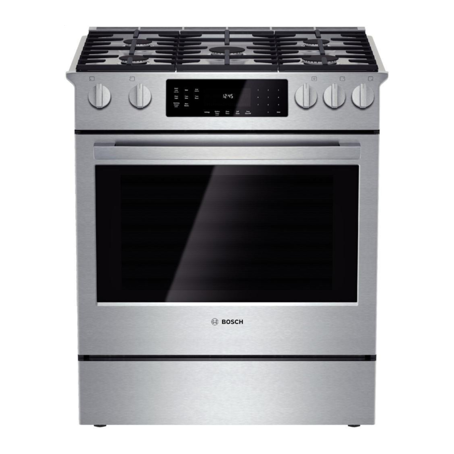
洗濯機 Bosch Vision 800 SeriesのPDF サービスマニュアルをオンラインで閲覧またはダウンロードできます。Bosch Vision 800 Series 36 ページ。 Gas slide-in ranges
Bosch Vision 800 Series にも: 取扱説明書 (40 ページ), 寸法と仕様 (2 ページ), インストレーション・マニュアル (6 ページ), サービスマニュアル (43 ページ), 取付説明書 (28 ページ)

58300000194725 ARA EN B
Always confirm that the range and all components are functioning
normally after setting the option code.
8.2.3 Displaying Error Memory
1. Follow the steps in the Accessing Service Mode section.
2. Advance through the menu until Error Memory is visible
3. Press (1) to show the error list; if no errors are logged, nonE
will be visible in the display.
Errors are displayed in numeric order; the error code (Exxx)
will appear on the left and the error count will appear on the
right of the display. (Example: E206: 003 indicates that error
code 0206 has been logged three times.)
4. Press (1) or (0) to cycle through the error memory list.
5. Press Enter to return to the initial Error Memory screen and
Enter again to advance to the next menu option.
8.2.4 Testing Relays
Refer to the table in the Accessing Service Mode section for a list of
relay test menu options.
1. Follow the steps in the Accessing Service Mode section.
2. Advance through the menu until Relay Tests appears in the
display.
3. Press (1) to begin testing.
4. Press Enter to navigate through the relay options.
The initial displayed state will reflect the current state of the
relay.
5. Press (1) or (2) to change the state of the relay.
6. After navigating through all relay tests, press Enter, then Enter
again to advance to the next menu option.
Copyright by BSH Home Appliances Corporation
This material is intended for the sole use of BSH authorized persons and may contain confidential and proprietary information. Any unauthorized review, use, copying, disclosure, or distribution in any format is prohibited.
MAY 2016
8.2.5 Testing Front Panel
The Front Panel Key Test will confirm that all control inputs are
connected and operating. The tests are based on the Option Code
that was set before entering Service Mode.
1. Follow the steps in the Accessing Service Mode section.
2. Advance through the menu until Key Test appears in the
display.
3. Press (1) to begin testing..
4. When the test is successfully completed, Key Test appears in
the display again. Press Enter, then Enter again to advance to
the next menu option
To exit the test, it must either be successfully completed
or the power must be reset.
8.3
The wire color key (Table 10) and element strip diagrams are shown
below. For schematics, please refer to the Slide-in Range Service
Guide, which can be found on QuickFinder or attached to the vented
housing panel in the rear of the range.
Wire Color Key
BK
GN
RD
YE
OR/BK
Table 7 Wire color key
1901 Main St ▪ Suite 600 ▪ Irvine, CA 92614
Service Manual for Bosch 800 Series Gas Slide-in Ranges
Wiring Diagrams and Schematics
BN
Black
Brown
Green
GR
Gray
Red
VT
Violet
Yellow
BN/WH
Brown/White
Orange/Black
VT/WH
Violet/White
BU
Blue
OR
Orange
WH
White
BU/WH
Blue/White
YE/BK
Yellow/Black
Page 35 of 36
800 944-2904
