- ページ 4
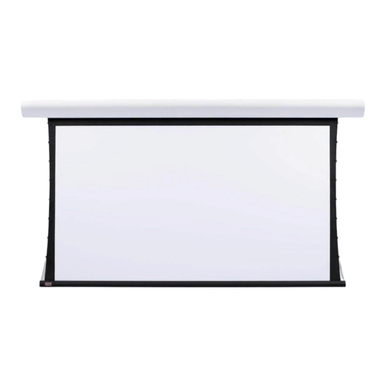
投影スクリーン Draper Silhouette E SeriesのPDF 設置および操作説明書をオンラインで閲覧またはダウンロードできます。Draper Silhouette E Series 4 ページ。 Electric projection screen
Draper Silhouette E Series にも: 取付・取扱説明書 (5 ページ)

Silhouette/Series E & V by Draper
Single Station Control
To 110-120V Line
Control
Switches
24v DC
STOP
STOP
Case Dimensions
4¾"
Silhouette
6"
Series E
Series V
Series E Viewing Surface Shown; Series V with Tab Tensioning also available.
At left, Series V slat bar is depicted inside case. Series E has a typical round bottom dowel.
For all Silhouettes, the dowel is concealed inside the case.
Wiring Diagram
Internal Screen Wiring
White (Common)
Black (Down)
Red (Up)
Green (Ground)
Dashed wiring
by electrician
Single gang box by others
Control
1
7
Min. 4" x 2
/
" x 1
/
8
switch
Blue
Red
Black
Location of key
operated on-off
switch if furnished
Low Voltage (& Wireless) Control Wiring Diagram
Low Voltage Control Module
Black (DN)
Black (DN)
Black
Red (UP)
Red (UP)
Red
White (COM)
White (COM)
White
Black (DN)
Red (UP)
White (COM)
Optional
Radio
Receiver
Package
7
/
" holes for supply wires located on back
8
and top, 2
D
5
5
/
"
16
Varies
D
Viewing Surface
Multiple Station Control
Red
" deep
8
Black
Red
Black
Red
Black
Location of key
operated on-off
switch if furnished
To 110-120V Line
White
Red
Brown
Black
Yellow
Green
Optional Infrared
Dashed wiring by electrician
Receiver Package
Location of key
operated on-off
switch if furnished
To 110-120V Line
1
/
" from left end of case.
2
Internal Screen Wiring
White (Common)
Black (Down)
Red (Up)
Green (Ground)
Cap off with wire
nut and tape
Blue
Dashed wiring
by electrician
Blue
Blue
Single gang box by others
1
7
Min. 4" x 2
/
" x 1
/
" deep.
8
8
3 shown. More or less equally
feasible.
Internal Screen Wiring
White (Common)
Red (Up)
Black (Down)
Green (Ground)
Page 4 of 4
