- ページ 19

オーブン Bosch FAP-OC 500SeriesのPDF 製品情報をオンラインで閲覧またはダウンロードできます。Bosch FAP-OC 500Series 40 ページ。 Built-in wall ovens
Bosch FAP-OC 500Series にも: 取付説明書 (21 ページ), 取扱説明書 (40 ページ), インストレーション・マニュアル (6 ページ), インストレーション・マニュアル (28 ページ), ユーザーマニュアル (48 ページ), ユーザーマニュアル (48 ページ), インストレーション・マニュアル (28 ページ), 取扱説明書 (44 ページ), インストレーション・マニュアル (32 ページ), 取扱説明書 / 設置手順書 (40 ページ), クイック・リファレンス・マニュアル (4 ページ), 取扱説明書 (27 ページ), インストレーション・マニュアル (24 ページ), インストレーション・マニュアル (32 ページ), 取扱説明書 (24 ページ), インストレーション・マニュアル (28 ページ), サービスマニュアル (41 ページ), 取扱説明書 (21 ページ), インストレーション・マニュアル (32 ページ), サービスマニュアル (36 ページ), インストレーション・マニュアル (32 ページ), クイック・スタートと安全マニュアル (13 ページ)
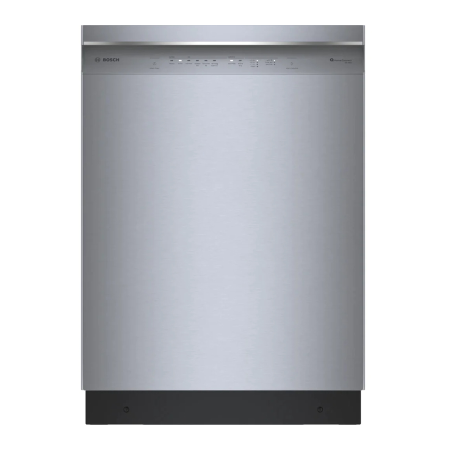
Bosch FAP-OC 500Series 製品情報
Product Information 500 Series LSN Fire Detectors (EU)

5.2. Detector Base / Detector Base with Relay

The base housings (Fig. 7.: Side view of
base) are made of white polycarbonate.
The screw terminals (for cables with cross sec-
tion from 0.3 mm
cure electrical connection through the clamped
contacts when mounting the detector.
The bases are provided with three mounts
for cable ties.
. These can be used for fastening the base during the wiring−up.
Detector bases with relay (FAA−500−R und FAA−500−R−GB) can
only be used in combination with the modular fire panel series 5000.
In cases where relay bases are used, no external detector alarm
display can be connected.
Connecting the base
D Wire up the LSN base according to the labeling in the outer ring (see Fig. 8.,
Pos. 3).
Fig. 8.: Plan view base
Pos. Description
1
Connection terminals
2
Mount for cable ties
3
Labeling on LSN connec-
tions
4
Fastening slot
2
2
to 3.3 mm
) guarantee a se-
Page 19
7.
1
2
3
4
8.
PI − 34.70 en
146 mm
BDL−F.01U.025.876
A5.en/ 02.02.2006
ST−FIR/PRM1 / zab