- ページ 2
アクセサリー BD Sensors DM 10のPDF 取付方法をオンラインで閲覧またはダウンロードできます。BD Sensors DM 10 2 ページ。 Digital pressure gauge
BD Sensors DM 10 にも: 取扱説明書 (2 ページ)
D
E
Montageanleitung /
Mounting instructions
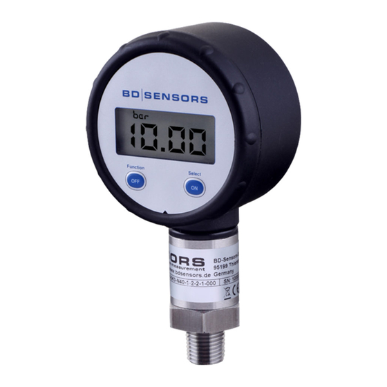
Digitalmanometer / Digital pressure gauge
DM 10
www.bdsensors.com
Zentrale
Headquarters
BD SENSORS GmbH
BD-Sensors-Str. 1
D - 95199 Thierstein
Deutschland / Germany
Tel.: +49 (0) 92 35 / 98 11-0
Fax: +49 (0) 92 35 / 98 11-11
Osteuropa /
Russland /
Eastern Europe
Russia
BD SENSORS s.r.o.
BD SENSORS RUS
Hradištská 817
39a, Varshavskoe shosse
CZ - 687 08 Buchlovice
RU - Moscow 117105
Tschechische Republik /
Russland /
Czech Republic
Russia
Tel.: +42 (0) 5 72 / 4 11-0 11
Tel.: +7 (0) 9 59 81 / 09 63
Fax: +42 (0) 5 72 / 4 11-4 97
Fax: +7 (0) 9 57 95 / 07 21
Diese Montageanleitung stellt einen Auszug
aus der ausführlichen Betriebsanleitung dar.
Bitte laden Sie sich diese auf unserer Home-
page herunter, falls Sie nicht mit dem Produkt
vertraut sind.
These mounting instructions are an excerpt from the complete
operating manual. It may be downloaded from our homepage, if
you are not familiar with the device.
http://www.bdsensors.de
http://www.bdsensors.com
– Technische Änderungen vorbehalten –
– Technical modifications reserved –
Englisch
WARNING! In order to avoid hazards to operators and
damages to the device, the following instructions have to
be performed by qualified technical personnel.
WARNING! Adhere to the safety and operating instructions
stated in the operation manual. Effective regulations on oc-
cupational safety, accident prevention as well as national
installation standards and approved engineering tech-
niques must in addition be complied with.
Limitation of liability
If the instructions in the operating manual are not adhered
to or if the device is inappropriately used, modified or dam-
aged, liability is not assumed and warranty claims will be
excluded.
Intended use
Ensure that the medium is compatible with the media-
wetted parts and that the device is suitable for the applica-
tion without restrictions. The technical data listed in the cur-
rent data sheet is binding and must definitely be observed.
Product identification
serial
input
type designation
ordering code
number
Changing the batteries
To change the battery go ahead as follows:
- Remove the cap and change the battery.
- Lock the device after that properly.
Structure of the menu system
Mounting
WARNING! Install the device only in depressurized and currentless state!
WARNING! Use a suitable seal, corresponding to the medium and the pressure input.
DO NOT USE ANY ADDITIONAL SEALING MATERIALS; LINKE YARN; HEMP OR TEFLON TAPE
(for connection acc. DIN 3852)!
Connection acc. to DIN 3852
NPT connections
G1/4":approx. 5 Nm
1/4" NPT: approx. 30 Nm
The indicated tightening torques must not be exceeded!
Display and operating module
Display
Select / ON -button
Function / OFF -button
Select / ON-button:
Function / OFF-button:
- switch-on of the device
- switch-off of the device
- choosing of the pressure units
- scrolling in the menu system
- calibration of starting point
- configuration of the switch-off automatic
Structure of the menu system
1 MIN
Minimum pressure display
The minimum pressure during the measurement process will be shown in the display.
To delete the stored value push the Select/ON-button. It appears
been recessed.
2 MAX
Maximum pressure display
The maximum pressure during the measurement process will be shown in the display.
To delete the stored value push the Select/ON-button. It appears
been recessed.
Setting of the pressure unit
3 UNIT
Possible units are: bar, mbar, psi, MPa, mH
The desired unit may be selected and activated with the Select/ON-button.
Depending on the nominal pressure range and the accuracy of the device, perhaps not all available
units could be used.
4 ZERO
Zero point
If you detect a shifting of the measured value deviating from the offset, the display can be re-calibrated via
pushing the Select/ON-button. The display shows
point from the ambient pressure, it is a pressure reference necessary.
5 SW OFF
Configuration of the switch-off automatic
The desired switch-off automatic may be selected through the Select/ON-button.
Allocation of the programmable values:
"0": switch-off automatic is not active
"1" – "5": switch-off automatic after 1 up to 5 minutes
The menu system will be leaved automatically after 10 seconds, the last setted value has been saved. If you scroll all menu
SW OFF
points you will leave the menu system after
After configuring the unit, the conversion of the pressure range into the new unit will only occur after leaving the menu
system. Depending on the pressure range, probably not all available units can be used.
Take note that no inadmissibly high mechanical
stress occurs at the pressure port, since this
may cause a shifting of the characteristic curve
or to the demage. This is especially important
for very small pressure ranges as well as for
devices with a pressure port made of plastic.
For more information, please read the detailed
operating manual!
Positioning of the display module
The display module of the pressure gauge is rotatable so that
clear readability is guaranteed even on unusual installation
positions.
in the display, the value has
in the display, the value has
O
2
, the value has been recessed. Differs the zero
.
MA_DM10_070213