- ページ 3
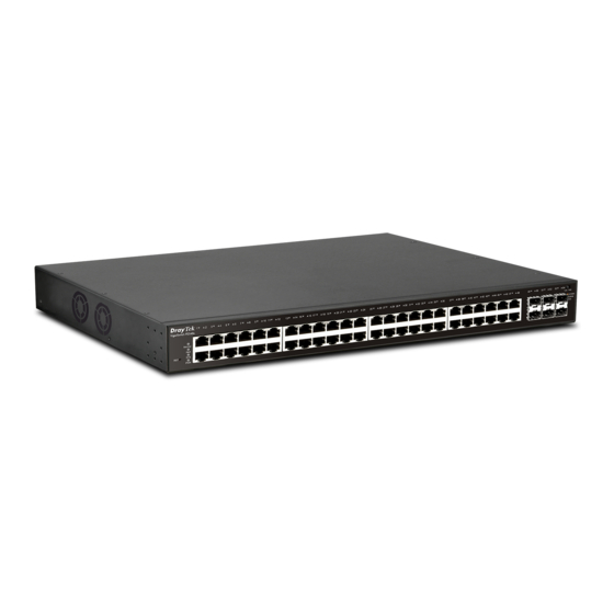
スイッチ Draytek VigorSwitch P2540xsのPDF クイック・スタート・マニュアルをオンラインで閲覧またはダウンロードできます。Draytek VigorSwitch P2540xs 9 ページ。 L2+ managed switch

2
.
P
a
n
e
l
E
2
.
P
a
n
e
l
E
Status
LED
On (Red)
Monitor
Off
Blinking (Green)
Alert
Off
On (Green)
Blinking (Green)
SYS
Off
On (Green)
PWR
Off
On (Green)
PoE Port 1 ~ 48
Off
On (Green)
Port 1 ~ 48
On (Amber)
(GbE RJ45)
Blinking
Off
On (Green)
Port 49 ~ 54
On (Blue)
(SFP+)
Blinking
Interface
RST
Port 1 ~ 48 (PoE)
Port 49 ~ 54 (SFP+)
Slide Switch
Console
x
p
l
a
n
a
t
i
o
n
x
p
l
a
n
a
t
i
o
n
PoE Port 1 ~ 48
Port 1 ~ 48 (GbE RJ45)
Explanation
An alert for system failure due to overheating or wrong
voltage.
The device is in normal condition and running normally.
The power is over (>) 80% watts PoE power budget.
The power is under (<) 80% watts PoE power budget.
The switch finishes system booting and the system is ready.
The switch is powered on and starts system booting.
The power is off or the system is not ready /
malfunctioning.
The device is powered on and running normally.
The device is not ready or is failed.
The port is supplied with PoE power.
No PoE power is supplied on the port.
The device is connected with 1000Mbps.
The device is connected with 10/100Mbps.
The system is sending or receiving data through the port.
The port is disconnected or the link is failed.
The device is connected with 1000Mbps.
The device is connected with 10Gbps.
The system is sending or receiving data through the port.
Description
Restore the default settings.
Port 1 to Port 48 can be used for Ethernet connection and
PoE connection, depending on the device connected.
Port 49 to Port 54 are used for 10G/1000M fiber
connection.
Switch the LED function.
Right: PoE connection status.
Left: LAN port connection status.
Used to perform telnet command control.
Power inlet for AC input (100~240V/AC, 50/60Hz).
3
Port 49 ~ 54 (SFP+)
