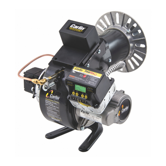
Fig. 1
TYPICAL FLANGE APPLICATIONS
UNIVERSAL
FLANGE
MOUNTING
PLATE
OPENING
ÿ
REFRACTORY
OR
HIGH TEMP
INSULATION
53/4— 7%
DRILL
a
tap
3 HOLES
r*
3/8
-
16
FLANGE
MOUNTING
PLATE
ASSEMBLING THE
BURNER
(Cont.)
2. Remove
the main housing assembly from the
larger
carton.
3.
Install the nozzle.
a.
Loosen the clamping screw on the
retention ring
assembly and
slide the retention
ring off the adapter.
b.
Install
and tighten
the proper nozzle
(45°
S-S Hago)
in the
adapter. Be careful
not to
damage the elec¬
trode insulators or
to
bend the wires.
c.
Replace the retention ring assembly, slipping one of
the riveted
arms
through the 14 -inch gap between
the electrode ends. This
top
arm
should be straight
up.
Also be
sure
that the retention
ring clamp is
tight
against the shoulder on the adapter. Then
tighten the clamping
screw.
4. Check the electrode settings specified
as
follows:
Vs
-inch
gap, 14
-inch above the nozzle centerline,
and
14-
to
5/16-inch ahead
of the nozzle
tip.
See Fig. 2.
Fig. 2
5. Swing open the transformer, and slide the nozzle line
assembly into the air tube.
Do
not
force
it. The flame
retention ring
must
be lifted and guided through the
throttle ring
(a
reduced
diameter)
in
the end of the
air tube.
6. Place the nozzle line yoke in the groove in the adjusting
screw.
7.
Swing the transformer
to
the closed
position
and fasten.
8. Connect the flared fitting
on
the copper oil
line
to
the
nozzle line and tighten.
ABOUT COMBUSTION CHAMBERS
Models
200CRD and 201 CRD operate
with superior effi¬
ciency and
cleanliness in properly designed refractory-type
combustion chambers. Very wide tolerance
to
burner
adjustments and other variables is found when these cham¬
bers are used. Noise levels are also reduced.
Table
1, page 3, shows the recommended minimum
in¬
side dimensions
for refractory brick, refractory
pre-cast,
and pre-formed refractory fiber chambers. Due
to
their
quick warm-up properties,
the lightweight insulating-type
materials
are
slightly preferable although these burners
show less dependence
upon refractory temperature than
previous models. Refractory materials in boilers and fur¬
naces
should
be capable of withstanding
2600°F
(
1427°C).
The
notes
accompanying Table
1
provide further details
relative
to
variations in dimensions
and
geometry.
Refer
to
Figs.
3 and 4, page 3.
FIRING BOILERS WITHOUT REFRACTORY CHAMBERS
Depending upon the
geometry
of the
combustion
space
some units perform better than others without refractory.
When the back wall
of
the unit coincides approximately
with the end of the flame,
a target
of refractory
material is
essential. Zero smoke readings
are
made easier if
a
refrac¬
tory
fiber "rug"
or
fill material
is used on the base under
the flame.
Table 2, together with its footnotes, gives the essential
dimensions and information needed
to
provide conditions
for satisfactory operation without complete
chambers.
Refer
to
Figs.
5, 6, 7, and 8, page 3.
INSTALLING THE BURNER: FLANGE MOUNTED
I. Measure, in
the burner opening, the distance from the
inside
of
the combustion chamber
to
the outside
of the
mounting plate
to
find the insertion length of
air tube
needed. Position flange
on air
tube
at a
point from
end
of
burner
corresponding
to
this
measurement.
Tighten
set
screws
to
anchor flange. The
flange is now located
so that
the
end of the burner
will
be flush, or almost
flush, with the inside of the
combustion chamber.
See
Fig. 4 (side
view) page
3, and Fig. 9, page 4.
2. Slide the end of the air tube into the opening and secure
the
flange
to
the front plate using three %-16 cap screws
(or
studs and
nuts)
provided.
(Continued, page 4)
2