- ページ 7
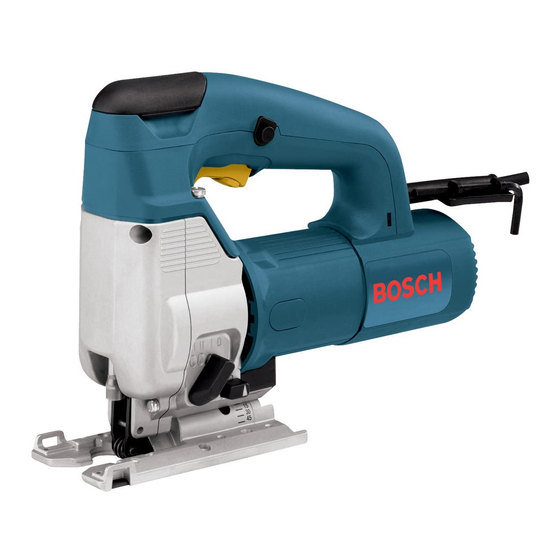
電動工具 Bosch 1587VSのPDF 取扱説明書をオンラインで閲覧またはダウンロードできます。Bosch 1587VS 33 ページ。 Operating instructions

BM 2610993477 2-04
2/9/04
BLADE INSTALLATION
Set the blade orbit selector lever to position III.
Pull blade change knob upward as far as it will
go and turn it three turns counter-clockwise
(viewed from the top of the tool).
Insert the blade into blade plunger at a 90˚
angle to the cutting direction. With a slight
upward pressure, turn the blade teeth forward
(direction of cut) and guide the back of the
blade into the groove in the center of blade
roller guide. Pull gently down on the blade to
seat the blade tabs in the plunger.
With the blade in the proper position, turn
1.
2.
VARIABLE SPEED CONTROLLED
TRIGGER SWITCH
Your tool is equipped with a variable speed
trigger switch. The tool can be turned "ON" or
"OFF" by squeezing or releasing the trigger. The
speed can be adjusted from the minimum to
maximum nameplate RPM by the pressure you
apply to the trigger. Apply more pressure to
increase the speed and release pressure to
decrease speed.
"LOCK-ON" BUTTON
The "Lock-ON" button, located in the handle
of your tool allows for continuous operation at
maximum RPM without holding the trigger.
TO LOCK TRIGGER "ON": squeeze trigger,
depress button and release trigger.
TO UNLOCK THE TRIGGER: squeeze trigger
and release it without depressing the "Lock-
ON" button.
If the "Lock-ON" button is
WARNING
!
continuously being depressed,
the trigger can not be released.
TRIGGER PRESET SPEED ADJUSTING DIAL
This feature enables you to preset the trigger
at desired speeds by rotating the dial on the
trigger to a higher or lower setting. Regardless
of the the pressure applied on trigger, the tool
will not operate any faster that the maximum
speed setting selected.
9:24 AM
Page 7
Assembly
knob clockwise until a noticable "Clic" noise is
heard, indicating that the blade is locked in
place. Depress knob to disengage and
continue to turn knob until it is aligned with the
curvature of the handle, and can be pressed
back into its normal position. Press down on
knob until it is flush with the handle, and the
jigsaw is ready for use.
Removing the blade is essentially the reverse
of the installation procedure, however, take
note that once the blade change knob is
loosened, gently push the blade upward to
release the blade tabs from the plunger.
3.
3x
Operating Instructions
Setting
A-B
Low stroke
C-D
Medium stroke
E
High stroke
The jigsaw cutting speed or stroke rate
required depends on the material being cut,
the type of blade used, and the feed rate
preferred by the operator. The best speed for
a particular application is largely determined by
experience, though as a general rule, slower
speeds are for denser materials and faster
speeds for soft materials. Note that when the
jigsaw is used at low speed settings for any
length of time, the motor temperature will rise
due to the slower speed of the internal cooling
fan.
In such cases, it is necessary to
occasionally run the tool at full speed for a few
minutes to keep the motor operating at high
efficiency.
Maximum cutting efficiency can be obtained
by adjusting the blade orbit selector lever to
suit the material being cut. The following chart
will help you determine which setting to use for
your application. This chart is intended as a
guideline only, and test cuts in scrap material
should be performed first to determine the
best setting.
Setting O hard materials such as metals or
-7-
5. 5.
4.
clic
PLUNGER SPEED
BLADE ORBIT
