- ページ 8
コントローラー Athena 2000 SeriesのPDF 取扱説明書をオンラインで閲覧またはダウンロードできます。Athena 2000 Series 20 ページ。 Temperature/process controller
Athena 2000 Series にも: 操作マニュアル (16 ページ)

Operation
NOTE: To reach
the plug-in module,
push reset button
while opening the
door, and then
remove two (2)
screws.
8
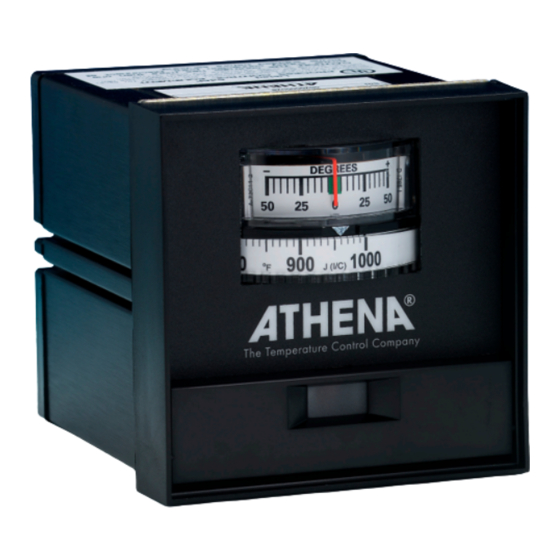
The typical control system contains the sensor, controller (2000/3020)
and the process (load). The sensor produces a small signal propor-
tional to the measured temperature of the process. This signal is
amplified by the controller, where it is compared with setpoint tem-
perature. If the temperature of the sensor is below setpoint, the out-
put circuitry will be actuated to apply power to the process. This is
indicated by means of an LED light in the lower center of the front
panel. The deviation meter will swing to the extreme left. It will remain
there until the temperature of the probe rises to within 50 °F of set-
point, and then will continue to rise to the null point (zero degree
deviation). The deviation meter accurately displays the difference
between the probe's (process) temperature and the desired setpoint
temperature.
-B - Relay Output
The "B" output is a relay rated at 7 A, 120 Vac and 5 A, 240 Vac.
These contacts can be wired to provide power to a heater within the
above rating. A contactor can be operated to handle a larger load.
Solenoids can be operated to control oil or gas heaters.
The controller operates as a narrow band controller when the band
adjustment is set at the narrow position. As the band is widened, the
unit becomes a time-proportioning controller, which provides close
temperature control. The percentage of the time when the relay is
energized is varied by the controller to meet the load requirements.
Maximum cycle time setting is 15 seconds.
-F - Current Output
Current proportional output of the -F unit is a 4 to 20 mAdc signal into
1000 ohm maximum. This output can be used to drive power con-
trollers, motor positioners or electropneumatic actuators.
-S - Pulsed Voltage Output
This output is similar to the -F output with the exception of a pulsed
time base rather than a fully proportional current output signal. This
output is designed to drive solid state contactors.
-L - Limit Control Output
The -L output unit is designed as a high limit controller and is a varia-
tion of the -B output controller. The time proportioning circuit, along
with the proportional band and offset (manual reset) adjustments,
have been eliminated. A reset pushbutton has been added to the
front panel and extends beyond the door. When power is applied, the
controller will energize except for the output relay, which will operate
after the reset button is pushed. The green LED indicates the safe or
non-alarm condition. When the measured temperature exceeds the
setpoint, the relay will de-energize and the green LED will turn off.
Lights or horns can be driven directly, because the SPDT relay con-
tacts are rated 7 A at 120 Vac or 5 A at 240 Vac.
-T - Solid State Output
The -T output unit has a solid state relay with SPST contacts rated at
1 A, 120/240 Vac (10 A inrush maximum). These contacts can be
wired to provide power to a heater within the above ratings, and a
contactor can be added to handle larger loads. Solenoids can be
operated to control oil or gas heaters.
