- ページ 5
アンプ ATI Audio MCDA-208のPDF 取扱説明書をオンラインで閲覧またはダウンロードできます。ATI Audio MCDA-208 15 ページ。 Ultra-low-jitter studio master clock dual 1x4 aes/ebu distribution amplifier

Since the purity of the clock reference is critical to the quality of the finished audio product, ATI
has taken steps to assure that the MCDA generates the lowest jitter clock reference available.
The MCDA's internal reference is derived from a 24 MHz precision oscillator and divided down
to achieve an ultra-stable signal, rather than multiplying up from a base reference as in some
other units.
The MCDA's Clock Distribution Amplifier has both Input and Loop-thru outputs to allow
downstream equipment to be fed from the input reference signal. When no downstream
equipment is connected, the inputs should be terminated via the front panel Input Termination
switch.
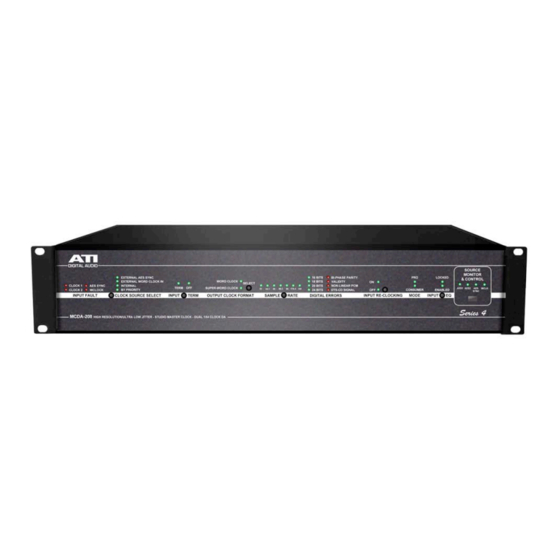
When fed from an external reference signal, the MCDA will indicate the clock frequency of the
input signal from 32 through 192 kHz. The full diagnostics front panel will also indicate Word
Length, Digital Errors if any, and whether the digital stream is Pro or Consumer mode. These
diagnostic indicators are switchable to display these details for either Clock input, or for the AES
External Sync In or Word Clock input.
The MCDA can also derive a Frame Clock (Word Clock) from the Clock signal input to Clock 1.
This Frame Clock signal is available for routing to all BNC outputs.
Clock 1, AES SYNC IN, and WORD CLOCK IN will lock to AES3, AES11 or Word Clock. AES
SYNC IN, and WORD CLOCK IN generate "Word Clocks" to be outputted.
Alarm LEDs located on the left side of the front panel indicates loss of carrier occurring on any
input, regardless of the position of the Source Monitor selector.
A front panel lock switch protects all settings. The MCDA retains all of its settings, even if power
is removed.
INPUTS
Incoming Clock formatted digital audio data, AES11 or Word Clock is applied to individual
input transformers. Input termination resistors at 75 ohms for BNC inputs can be switched
in or out of the circuit with the front panel Input Term switch. Inputs should always be
terminated unless they are looped through to another device or a second MCDA input.
OUTPUTS
The MCDA has eight balanced, transformer driven XLR outputs arranged in groups of four;
i.e., 1 through 4 and 5 through 8. It also has eight isolated BNC outputs which function as a
single group. Rear panel mounted DIP switches allow you to configure the MCDA to send
the following signals to any or all of these three groups of outputs:
1. CLOCK INPUT 1
2. CLOCK INPUT 2
3. AES SYNC-IN Clock derived Word Clock
4. WORD CLOCK INPUT External Word Clock
5. Internal Clock Generator
6. Clock 1 derived Frame Clock
It is not necessary to terminate unused outputs, as each is individually isolated.
POWER
Connector for socket fused IEC 320/C13. Power cord is supplied. The MCDA has a rear panel
On Off power switch.
5
!
"#$%&'()!"*+,*-!
!
