- ページ 11
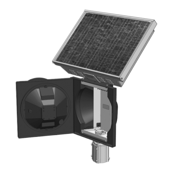
インバーター Carmanah R247-FのPDF インストールマニュアルをオンラインで閲覧またはダウンロードできます。Carmanah R247-F 20 ページ。 Traffic beacon
Carmanah R247-F にも: クイック・スタート・マニュアル (20 ページ), エネルギー管理システム交換マニュアル (12 ページ), インストールマニュアル (20 ページ)
• Obtain 3" of red wire supplied with the kit and strip both ends to 0.35".
• Insert one end of 3" red wire into PBS+ terminal.
• Route modified AI harness wires (from Steps 2 – 5, violet, blue, black, red and yellow)
into the hole shown.
10
• Install the wires into the terminals as follows:
Violet
3-position splice terminal with red wire going to PBS+
Blue
EXT1
Red
Middle BAT+
Black
Middle BAT−
If the system has a push
button, insert the positive
push button wire into the
empty position of the 3-
position splice terminal.
Carmanah Technologies Corp. | 250 Bay St, Victoria, BC V9A 3K5, Canada | 1.250.380.0052 | customerservice@carmanah.com | carmanah.com
Install AI Harness
Blue
(EXT1)
(PBS+)
Violet and
red (splice
terminal
• Align ends of heatshrink on both harnesses near end of
sheet metal tab.
11
• Cable tie around both harnesses and sheet metal tab.
APPLIED INFORMATION (AI) INTEGRATION INSTALL GUIDE
Red
Red
(BAT+)
F Series
Black
(BAT−)
Page 11