- ページ 6
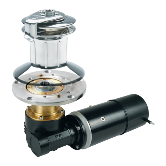
ウインチ Andersen RA2050001300のPDF 製品マニュアルをオンラインで閲覧またはダウンロードできます。Andersen RA2050001300 18 ページ。 To suit self-tailing winch sizes 46,50

INSTALLATION INSTRUCTIONS
STEP 1 - Positioning the winch and motor unit
• Position the winch drilling template [A3] in the required position on the deck, ensuring that there
is adequate flat space for the deck plate/ winch base.
• The 46 & 50 ST winches have the option of eight different self-tailing arm positions as indicated
on the drilling template (refer page 15).
• Considering the product dimensions, shown on page 14, check that there is adequate space
below deck for the motor unit. You may choose to drill a small pilot hole to indicate the position
of the center of the drive shaft, to assist with this.
*Note: The motor unit can be installed in eight positions around the center of the drive shaft
(i.e. at 45° increments), to facilitate fitting the motor unit into restricted under-deck cavities.
See page 14 for the minimum motor offset dimensions at the various positions. Placing the
winch base on the motor unit in the various positions prior to installation can assist with
visualising the motor position options.
*Note: To ensure the correct functioning of the winch, it should be positioned with the correct
line entry angle of 3-8° below horizontal. Refer to the winch product manual for details of
correct line entry angle and self-tailing arm positioning.
STEP 2A
• Remove winch self-tailing arm screws using 4mm Allen key [A4].
• Lift self-tailing arm and drum off the base/stem of the winch.
• Remove 6 x M6 screws from base of winch stem with 5mm Allen key [A5].
• Lift stem off base of winch and place aside.
• Remove rubber shut-off disc from base of winch.
STEP 2B - Fitting the winch base
• After it has been confirmed that there is adequate space for the winch above deck, and for the
motor unit below deck;
• Drill Ø8.5mm holes for the M8 winch base mounting bolts as per the drilling template [A3].
Drill Ø11/32" holes if 5/16" bolts are being used.
• Drill or cut a Ø82mm (3 1/4'') hole for motor drive shaft housing as per the drilling template.
*Note: Clean the deck hole before attempting the install the motor so that
the motor flange does not catch splinters of fiberglass or wood when being inserted through
the deck. Clean the deck with a suitable solvent to ensure the sealant can adhere properly.
• Apply sealant to the deck where the winch base will be fitted. For aluminium boats use a galvanic
isolating ring/gasket.
• Fit the winch base to the deck using appropriate length M8 (or 5/16") bolts, large backing washers
or plate, and Nyloc nuts.
• Assemble the winch in reverse order to the disassembly/removal.
E1 Single Speed Electric Motor Unit, 12V & 24V
To Suit Self-Tailing Winch Sizes 46,50
p6
