- ページ 4
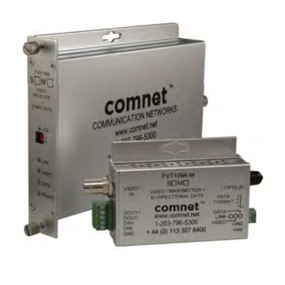
レシーバー Comnet FVR109AS1のPDF 設置および操作マニュアルをオンラインで閲覧またはダウンロードできます。Comnet FVR109AS1 7 ページ。 10-bit digital video with one bi-directional data channel

INSTALLATION AND OPERATION MANUAL
FIGURE 6 – DATA SWITCH POSITIONS
The mode for each data channel is configured using a pair of switches on the front panel of the unit.
Switch
FVT109A-M
FVT109A
FIGURE 7 – CONTACT CLOSURE
The FVT109A transmits the state of a contact closure input over fiber to an output relay on the FVR109A.
Dry contact closure input. Applying
a voltage to these pins may damage
the unit.
NOTE: It is possible to configure the FVR109A output relay to indicate the link status instead of
the contact closure input when linked to a FVT109A. Consult the factory for more information.
TECH SUPPORT: 1.888.678.9427
1) RS232
1
3) RS485 2-Wire,
Sensornet
1
FVR109A
1) RS232
DIN (–)
DOUT (–)
GND
2
2
2) RS422,
3) RS485 2-Wire,
Bi-Phase,
Manchester
DIN (+)
DIN (–)
DOUT (+)
DOUT (–)
GND
When linked to a FVT109A, the output
relay refl ects the state of the input
contact (open or closed). When linked
to a FVT109A-M, the output relay
indicates the state of the optical link.
The terminal pair is closed when the
optical port has established link, and is
open when the optical port has lost link.
FVT/FVR109A(M,S)1[M]
2) RS422, Bi-Phase or
Manchester
1
2
4) RS485 4-Wire
1
2
4) RS485 4-Wire
Sensornet
DIN (+)
DIN (–)
DIN (+)
DIN (–)
DOUT (+)
DOUT (–)
GND
GND
INS_FVT/FVR109A_REV–
11/28/10
PAGE 4
