- ページ 5
除湿機 Dri-Eaz DRITEC 325のPDF オーナーズマニュアルをオンラインで閲覧またはダウンロードできます。Dri-Eaz DRITEC 325 11 ページ。 Desiccant dehumidifiers
Dri-Eaz DRITEC 325 にも: オーナーズマニュアル (11 ページ)

tures down to freezing, so it may be effective even in un-
heated buildings.
Monitoring Specific Humidity Changes
For fast and complete drying, the specific humidity in the
area being dried should be monitored. Specific humidity
measurements can be obtained using a thermo-hygrometer
(such as the DHT 600) to obtain relative humidity and tem-
perature of the ambient air, plus a Psychrometric Calculator
or Chart.
Specific humidity readings (measured in grains per
pound) give a true indication of the amount of moisture in
the air. Relative humidity readings alone is not useful infor-
mation unless the temperature is always the same, wherever
and whenever a measurement is taken. This is seldom or
never the case in water damage restoration.
Moisture Content of Materials
The moisture content of structural materials should also
be monitored with a moisture meter such as the MoisturePro.
A moisture meter indicates the extent that these materials are
wet. It will assist you, and your customer, in determining
when the job is completely finished. A variety of moisture
meters are available from Dri-Eaz Products.
MAIN COMPONENTS
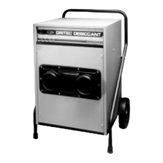
Figure 1 shows most of the important parts of the DriTec
Desiccant Dehumidifier: the rotor, process air stream, and
reactivation air stream. The DriTec Desiccant has seals sepa-
rating the two streams of air – the damp process air, and the
heated reactivation air. Notice that the two air streams move
through the DriTec Desiccant in opposite directions.
Air Filter
If the air in the room is dirty, the dirt can collect in and
plug the passages of the rotor. A cleanable foam air filter is
placed on the intake side of the rotor to catch dirt in the air
stream.
Process Air Outlets
Process air is vented from the DriTec through one or two
outlets, one of which is adjustable with a slide lever.
Reactivation Air Stream
The reactivation air stream uses approximately one-third
of the total air stream, which flows through electrical heating
elements and then through the rotor, where the heat reacti-
vates the desiccant. The air stream then passes through the
reactivation outlet and is vented through ducting to the out-
doors.
Rotor Drive
The rotor is turned by a small drive motor and belt. A
spring-type tensioner automatically adjusts the belt tension.
DriTec 150 Controls
The DriTec 150 is controlled by an on-off rocker switch
on the front panel. The switch is lighted red with the unit is
on and operating.
DriTec 325 Controls
The controls for the DriTec 325 are located on the front
panel. The main power switch has three positions:
COPYRIGHT © 1999 2000 DRI EAZ PRODUCTS INC
On – DriTec Desiccant operates continuously.
Off – Control system turned off. When the switch is turned
to Off after the unit has been running, the blower and drive
motor continue to run for 5 minutes to cool down the unit.
Then the unit automatically shuts off the blower and drive
motor.
Option – Provided only for use with a remote dehumidi-
stat which is not included with this unit.
Indicator Lights (DriTec 325 only)
The DriTec 325 has four indicator lights located on the front
panel:
Power Light – On when power to the unit is connected.
Unit On Light – On when main switch is turned to On or
Option, and the unit is operating.
Blower On Light – On when main switch is turned to On;
shows that the blower is operating. Stays on during cool-
down period after switch is turned off (about 5 minutes)
while blower and drive motor continue to operate until
automatic shut-off. Turns Off if the blower circuit is over-
loaded and open.
Heater On Light – On when main switch is turned to On;
shows that the heater is operating. Like the blower light,
stays on during the 5-minute cool-down period. Turns Off
if the heater circuit is overloaded and open.
Heating System
The heating system uses unique PTC-heating elements
which eliminate the need for conventional components for
temperature control and thermal safety. (PTC means positive
temperature coefficient; the element is a ceramic semi-
conductor.) These elements have a self regulating feature
which controls the output of the elements based on the re-
quired temperature. For instance, if the reactivation airflow
is reduced, the heater elements will react rapidly to the
higher temperature with an increasing electric resistance,
and automatically reduce the heat output. An overheating
protection thermostat is therefore not needed.
INSTALLATION & STARTUP
Inspection
When the unit arrives, check immediately for signs of
shipping damage. If you do notice any damage, report it to
the shipping company immediately. Notify Dri-Eaz Prod-
ucts, Inc. about the damage as soon as possible. If the unit is
damaged, do not discard the original packaging.
Positioning the Dehumidifier
The dehumidifier should be operated in a "closed sys-
tem" to achieve maximum efficiency. That is, all doors,
windows and other openings to the outside should be closed
tightly, with the exception of an opening for the reactivation
outlet (wet air) duct.
Locating the Dehumidifier
There are two options for locating the dehumidifier.
Typically, it will be placed directly in the humid environ-
ment. This allows the process air to be drawn from that area,
dried, and then returned to the same room.
5
