- ページ 4
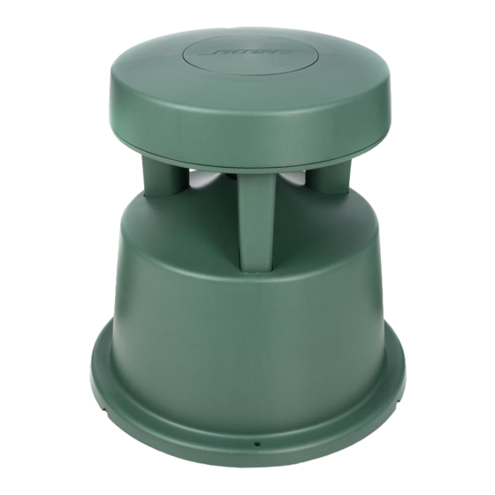
スピーカー Bose FreeSpace 360のPDF 補足マニュアルをオンラインで閲覧またはダウンロードできます。Bose FreeSpace 360 13 ページ。 Surface and in-ground loudspeaker eq cards
Bose FreeSpace 360 にも: サービスマニュアル (9 ページ)
These Equalizer cards are designed to be installed into the AmPlus™ 50 and 100 amplifiers
and the Bose
®
1600 Series VI and 1800 Series V/VI amplifiers.
®
The FreeSpace
360 loudspeaker requires equalization, and this equalization is a function of
the installation. There are two variants of the card that implement EQ curves for these
installation situations:
•
In Ground (when the FreeSpace 360 loudspeaker is mounted in the ground).
The appropriate EQ curve for soft or hard ground is selected with a slide switch on the card.
When S1 is in the SOFT position, the Soft Ground EQ is used; when S1 is in the HARD
position, the Hard Ground EQ is used.
•
In the Surface variant, S1 is omitted and jumpered to the SURFACE position.
Note: Refer to the FreeSpace 360 Surface or In-Ground schematic diagrams, as appropriate,
for the following explanation. The designators inside the brackets "[ ]" are the schematic grid
coordinates which are provided in order to make it easier to locate components on the
schematic sheet indicated in the description. Components shown on the schematic as
OPT (optional) are not used in that particular configuration.
The input signal is applied to these cards at JP1 pin 4. The first section at the input, U2-B [D7],
combines a first order high-pass filter with one section of a parametric cut filter. The parametric
is set for -15dB at 27Hz and provides a steep slope below about 80Hz. The equalization is
segmented, with one block (U2 and U1), all sections [D1-8] dedicated to bass region equaliza-
tion. Following the output of this section, U2-A [D1], the signal is presented to two parallel
equalization paths, one comprised of U3 [B4-7], U4-B [C3], and dedicated to EQ for mounting
in soft ground of the FreeSpace 360 loudspeaker. The other path, comprised of U5 [B4-7],
U4-A [B3] provides equalization for the FreeSpace 360 loudspeaker in hard ground installa-
tions. In the case of the FreeSpace Surface EQ card, the bottom leg of the equalizer card is
not used.
The operation of all three equalizers is similar. Considering the bass equalizer, we see U2-B's
[D7] output passed through R8 [D7] and into the non-inverting input of U2-A [D2]. This input is
extended as a bus to which EQ sections Bass 1 [D6] and Bass 2 [D5] are connected. These
will introduce dips into the audio response to provide bass cut as required. Sections Bass 3
[D4] and Bass 4 [D3] are connected to a bus extended from the inverting input of U2-A [D2]
and provide bass boost.
See Figures 1,2 and 3 for the EQ curves for the various equalizer cards.
Each of the EQ sections utilizes a gyrator-connected op-amp in conjunction with a series
capacitance to simulate an LCR series tuned circuit. The values of the capacitors and resistors
are chosen to implement EQ dips and/or peaks at the appropriate frequency, amplitude and Q
to realize the desired EQ curves. On the In-Ground EQ card, S1 [B2] selects either the HARD
or the SOFT mount EQ curve.
The output signal is taken from JP1 pin 5, and returns to the amplifier. The equalizer cards are
sensed by the amplifiers as follows. In the AmPlus 50 and 100 amplifiers, Pin 12 of J1 [B2] is
grounded and is sensed by the dynamic EQ circuit on sheet 2 of the AmPlus 50 and 100
schematic diagrams. In the 1600/1800 amplifiers, the input module detects the presence of EQ
cards via J7-6 and J6-6. Without the card installed these pins are pulled high (+15V). This logic
high signal is also applied to the control pins of the switch ICs which selects the A
(unequalized) input. When an EQ is plugged into J7 and/or J6 pin 6, the EQ is detected and
pulls the control pin low (+7.5V), turning on the corresponding LED(s) and switching the IC to
the B input which will then select the output of the EQ card to be passed on to the amplifier.
THEORY OF OPERATION
4