- ページ 6
スピーカー Bose LT 6403のPDF マニュアルをオンラインで閲覧またはダウンロードできます。Bose LT 6403 35 ページ。 Lt and mb series loudspeakers
Bose LT 6403 にも: インストレーション・マニュアル (32 ページ), インストレーション・マニュアル (32 ページ), オーナーズマニュアル (32 ページ)

Panaray
®
LT 6403 and LT 9403 Full-Range Loudspeakers
The Bose
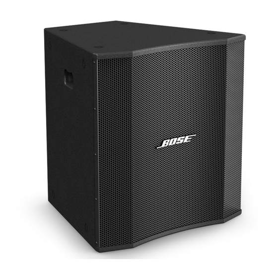
Panaray LT 6403 and LT 9403 Full-Range loudspeakers are full range, three way
®
devices. They use a 15" woofer, a V2 mid-frequency driver and a 1.0" compression driver
mounted on a 60 x 40 (LT 6403) or a 90 x 40 (LT 9403) constant directivity horn assembly.
This horn assembly can be rotated 90 degrees to allow sideways placement of the speakers.
These loudspeakers can be operated in passive or bi-amplified mode.
•
In passive mode, the internal passive crossover network is utilized and a single amplified
signal is connected to the loudspeaker.
•
In bi-amplified mode, the low-frequency and mid/high-frequency drivers are accessed
through separate pins on the NL4 connectors.
Panaray LT 6400 and LT 9400 Mid/High Frequency Loudspeakers
The Panaray LT 6400 and LT 9400 Mid/High Frequency Loudspeakers are essentially the same
as the LT 6403 and LT 9403 full range versions, but without the 15" woofer. They use a V2 mid-
frequency driver and a 1.0" compression driver mounted on a 60 x 40 (LT 6400) or a 90 x 40 (LT
9400) constant directivity horn. The horn assembly in the LT 6400 and LT 9400 can be rotated 90
degrees as in the LT 6403 and LT 9403.
Active equalization of all four loudspeakers can be provided by using the ControlSpace
or the Panaray Digital System controller which has presets for each Panaray speaker and
combination of speakers. A parametric equalizer can also replicate the active equalization curves
on the previous pages, along with high-pass and low-pass filters as shown.
All of these speakers have sixteen steel threaded inserts - four top, four bottom and four on each
side. Threaded inserts are SAE 3/8 - 16 thread, with at least 18 usable threads.
Hanging hardware for these speakers can be purchased from ATM Flyware at
http://www.atmflyware.com.
1. This part is not normally available from Customer Service. Approval from the Field Service
Manager is required before ordering.
2. The individual parts located on the PCBs are listed in the Electrical Part List.
3.
This part is critical for safety purposes. Failure to use a substitute replacement with the
same safety characteristics as the recommended replacement part might create shock, fire
and/or other hazards.
4. This part is referenced for informational purposes only. It is not stocked as a repair part.
Refer to the next higher assembly for a replacement part.
Product Descriptions
Part List Notes
6
ESP-88
TM
