- ページ 5
ツール Atlas Copco RTのPDF ユーザーマニュアルをオンラインで閲覧またはダウンロードできます。Atlas Copco RT 16 ページ。 Square drive hydraulic torque wrench system

The reaction arm for all RT Monobloc Housing is splined to slide over the rear (cylinder) portion of the tool. In
operation, the reaction arm must be fully engaged and secured by inserting the spring loaded reaction arm
lever at the base of the housing ( End Cap ). Ensure the reaction is fully engaged prior to operation.
3:4
SETTING TORQUE
Once the system is fully connected and proper power supply available, the operator may now adjust the
pump pressure to the level needed for the application.
When tightening, use the manufacturer's specifications to determine the torque value which you will
ultimately require.
Torque sequence may vary from plant to plant and even within individual plants, depending upon the gasket
material, etc. Always abide by local procedures.
Next, find the pressure-torque conversion table applicable to the tool which you intend to use.
3:5
SETTING WORKING PRESSURE ON THE PUMP
To set the pressure on the pump, follow this procedure:
1.
Loosen the knurled locking ring below the "T" handle on the pump's external pressure regulator. Then
turn the "T" handle counter clockwise (CCW) until it turns freely and easily.
2.
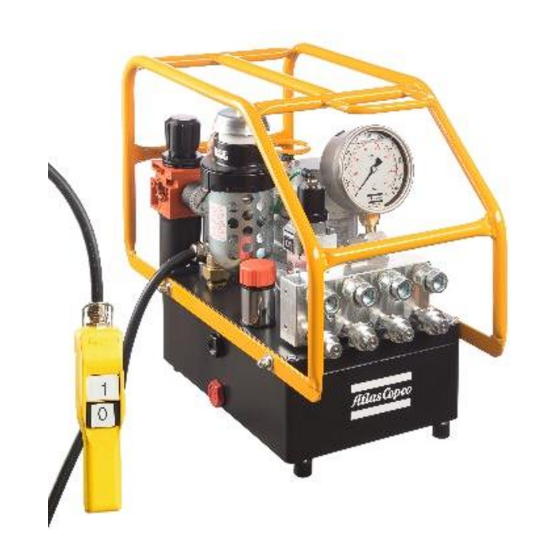
Turn the pump "on". Using the pump's remote control pendant, push down the advance switch (or button
on air pumps) and hold it.
3.
While holding the pump in the advance mode, slowly turn the "T" handle clockwise and observe the pump
pressure gauge rise. NOTE: Always adjust the regulator in order to increase the pressure up - Never
down. Never adjust the regulation with the tool on the application.
4.
When your gauge reaches 4,000 PSI stop turning the "T" handle and let the gauge settle out.
5.
If the pressure continues to rise (above 4,000), release the advance button and back off your pressure
slightly-by turning CCW on the "T" handle. Then re-depress the advance switch on you
remote and slowly bring pressure up to 4,000 again.
6.
When the pressure is correct, turn the pump "off" and tighten the knurled lock nut
provided under the "T" handle. This sets pump pressure, which determines torque tool
output.
Locking ring
T-Handle
3:6
APPLYING THE TORQUE MACHINE-TIGHTENING
Having set your target pressure, cycle the tool three or four times to full pressure. Cycling the tool ensures that
the system is operating properly and removes trapped air, if any.
Verify that any impact sockets used are rated to accept the full torque output of the tool they are to be used
with. Ensure the correct size impact socket for the nut A/F has been selected, placed on the square drive and
secure with a locking pin and ring.
Place the tool and the socket on the nut, making sure that the socket has fully engaged the nut, check that the
drive retainer is engaged.
Make sure the reaction arm is firmly abutted against a stationary object (i.e. an adjacent nut, flange, equipment
housing etc.). When positioning the wrench, make sure that the hose connections are well clear of any
obstructions and that all body parts are safely out of harm's way. THEN, AND ONLY THEN, apply momentary
pressure to the system to ensure proper tool placement. If it doesn't look or act right, stop and re-adjust the
reaction arm.
NOTE: Please read Safety Instructions supplied with the torque wrench for further guidance on tool usage
7.
Once your target pressure is set and locked, cycle the pump once more to
ensure that your pressure setting did not change as you turned down the knurled
knob.
5
