- ページ 26

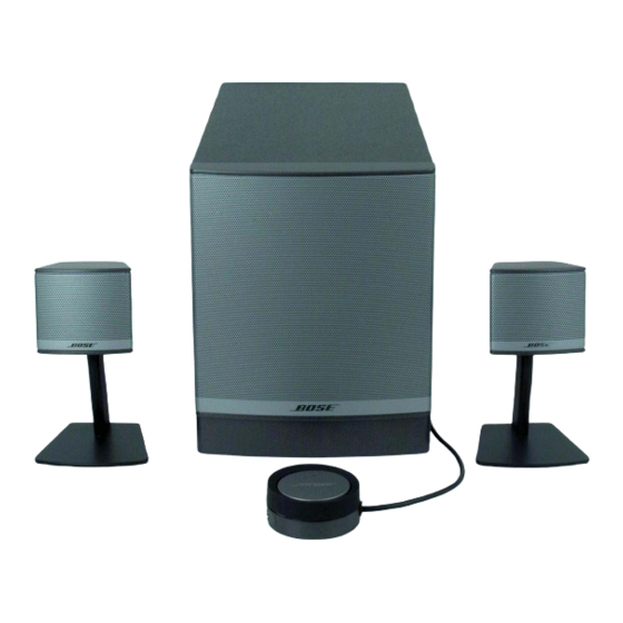
ステレオシステム Bose Companion 3 Series IIのPDF サービスマニュアルをオンラインで閲覧またはダウンロードできます。Bose Companion 3 Series II 36 ページ。 Multimedia speaker system
Bose Companion 3 Series II にも: オーナーズマニュアル (40 ページ), オーナーズマニュアル (40 ページ), オーナーズマニュアル (22 ページ), オーナーズマニュアル (10 ページ), オーナーズマニュアル (20 ページ), オーナーズマニュアル (26 ページ), クイック・セットアップ・マニュアル (2 ページ), クイック・セットアップ・マニュアル (2 ページ), 詳しい組み立て説明書 (2 ページ), インストレーション・マニュアル (20 ページ), 仕様 (6 ページ), パンフレット&スペック (4 ページ), オーナーズマニュアル (19 ページ), サービスマニュアル (16 ページ)

Bose Companion 3 Series II サービスマニュアル
®
The Companion
3 Multimedia Speaker System is a 2.1 system designed to be used as a computer
sound system.
The electronics contain signal processing circuitry and the amplifiers for the woofer and satellites. A
120 volt AC input, 14 volt DC power supply powers the electronics. The power supply is located on a
separate PC board.
The signal processing electronics in the bass module include equalizers, bass summing, TrueSpace™
processing, level compression, to prevent clipping at high volume, and protection circuitry.
The crossover frequency between bass and satellites is 300 Hz. The system is rated at 60 watts to
the woofer and 18 watts to each satellite. The bass box is tuned to 45 Hz.
The following is a detailed description of the circuitry on the power supply, amp board, and remote
board.
1.0
Power Supply (refer to the schematic diagram 276769)
The power supply is located on the heat sink of the module and is the smaller PCB of the two. The
120 volt AC is received from the AC inlet jack and switch at J1. The AC is fused by the 4 amp F1 fuse.
VR1 protects against high voltage surges. The 120 volts is sent out to the 15 VAC, 7 amp toroid
transformer mounted to the interior of the bass box on J2. The 15 VAC secondary voltage comes
back into the board on J2. The 15 VAC is converted to 15-20 volts DC by bridge rectifier BR1.
Q1, Q2 and Q3 form a pre-regulator to keep the DC output voltage at 14 VDC. The 13 volt zener D1
serves as a reference to Q1. When the input AC goes one diode drop above the zener voltage, Q1
turns on. This turns off Q2, allowing Q3 to turn off, which disconnects the input rectified AC from
charging C7, the 3300 uF filter capacitor above 14 volts. This makes the voltage at C7 stay at about
14 volts. C2, C3 and C4 slow down the turn on of Q3 to reduce interference from this circuit to the
amplifier.
When the rectified voltage is lower than 14 volts, Q1 turns off, turning on Q2 and then Q3, allowing
C7 to charge whenever the ratified voltage from BR1 is above the voltage left on C7. The 14 VDC is
sent to the amplifier board over J3.
RT1 is a 22K thermistor at room temperature. It is mounted on the heat sink between BR1 and Q3. It
senses the system temperature and sends a signal to the main amp board to help reduce system gain
when the heat sink is getting too hot.
2.0
Main Amplifier Board (refer the schematic diagram 276762)
On sheet 1 of 3, location (D8), is the A input. U3, (D7) buffers the inputs to be sent to the remote
control through J308. The remote mixes the A with the B input, on the remote, and sends the signal
back to the main PCB though J308. The control pod is further described in section 3.

Theory of Operation

26