- ページ 4
潤滑システム DROPSA 3135062のPDF ユーザー・メンテナンス・マニュアルをオンラインで閲覧またはダウンロードできます。DROPSA 3135062 11 ページ。 Oil lubrication system

6. UNPACKING AND INSTALLING THE PANEL
6.1 UNPACKING
Once a suitable location has been found to install the unit, remove the panel from package. Check the unit
has not been damaged during transportation or storage. No particular disposal procedures are necessary
as packaging materials are no dangerous for health or environment. However, package should be disposed
of in accordance with regulations that may be in force in your area or state.
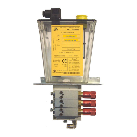
6.2 INSTALLING VIP4Tools/Oil PANEL
In order to facilitate any maintenance intervention and to avoid unnatural posture or the possibility of
sustaining impacts, install the machine in a reachable position.
Allow sufficient space for the installation, leaving minimum 100 mm (3.93 in.) around the unit.
Do not install the unit in aggressive or explosive/inflammable environments or on vibrating surfaces.
To install the panel, use only the supplied bracket provided with two holes for screws Ø6mm (Ø 0.23
in.), see Dimentions ch.12.
6.3 INSTALLING MINI-PUMPS ON THE SUB-BASE
Mini-pumps are assembled to sub-base by means of two fixing screws. Be careful to correctly posistion o-
rings between mini-pumps and sub-base, as shown in the figure below:
6.4 HYDRAULIC FITTING
Connect each mini-pump to the corresponding lubrication point using Ø4mm (Ø0.15 in.) nylon piping
(furnishable by Dropsa).
6.5 PNEUMATIC CONNECTIONS
Connect the air inlet to push-in by mounting Ø 6mm (Ø 0.23 in.) nylon piping on the sub-base. A check valve
must be arranged in order to stop air supply.
6.6 ELECTRIC WIRING
Samba level is the only electric connection for VIP4Tools/Oil (see the electric diagram below).
At the end of all connecting operations, make sure that pipes and wires are safe from impacts and
carefully fixed.
4
