- ページ 5
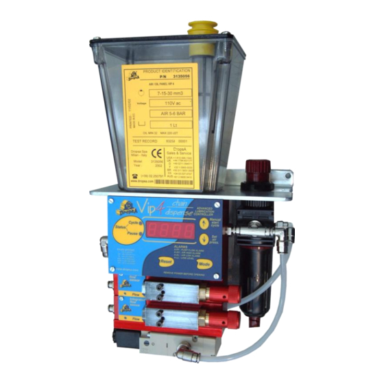
潤滑システム DROPSA 3135125のPDF ユーザー・メンテナンス・マニュアルをオンラインで閲覧またはダウンロードできます。DROPSA 3135125 14 ページ。 Chain lubrication & dispensing

6.5 HYDRAULIC CONENCTIONS
It is suggested to use Ø4 mm tube on the air/oil outlets located on the left hand side of the unit.
6.6 PNEUMATIC CONENCTIONS
Connect the Air inlet to the solenoid inlet on the base of the unit using Ø6 mm nylon tube.
6.7 ELECTRICAL CONNECTIONS
Before carrying out any type of electrical wiring – ensure that all power is removed from the machine.
Ensure also that the voltage you are using matches that which is indicated on the unit. A label next to the connector
also indicates the correct operating voltage of the model you have purchased.
NB: The female connector is purchased separately.
Follow the diagram below to complete the electrical connection.
LEFT HAND SIDE CONNECTOR : Used for input power and remote alarm signal.
1639115 – Optional connector and 2m cable assembly
BOTTOM CONNECTOR – Located on the rear power box, located on the bottom face . This is used to connect a
remote switch or proximity switch to count impulses from the Chain and time the lubrication cycle.
3194002 – Connector for signal
NB: After all connections have been completed ensure the tubing and cables are protected from impacts and are
suitably secured.
Female
1639121
L=2m
Female
Male
Pin n°
Male
1
2
3
4
5
6
Pin n°
1
2
3
4
5
6
Vers. 24V
Vers. 110V
0 V
24 Vdc
/
/
110 Vac
ALARM NC Contact
ALARM – Common Signal
ALARM – NO Contact
Earth
Signal
0 V
+ 12 V dc
SIGNAL IN.o
Not used
Not used
Not used
Earth
5
