- ページ 11

扇風機 Daikin R32 Split SeriesのPDF インストレーション・マニュアルをオンラインで閲覧またはダウンロードできます。Daikin R32 Split Series 14 ページ。 R32 split series
Daikin R32 Split Series にも: インストレーション・マニュアル (17 ページ), インストレーション・マニュアル (16 ページ), インストレーション・マニュアル (16 ページ), インストレーション・マニュアル (16 ページ), インストレーション・マニュアル (17 ページ), インストレーション・マニュアル (16 ページ), インストレーション・マニュアル (20 ページ), インストレーション・マニュアル (14 ページ), 操作マニュアル (16 ページ), 操作マニュアル (16 ページ), 操作マニュアル (8 ページ), インストレーション・マニュアル (17 ページ), インストレーション・マニュアル (16 ページ), インストレーション・マニュアル (20 ページ), インストレーション・マニュアル (20 ページ), インストレーション・マニュアル (16 ページ), インストレーション・マニュアル (16 ページ), インストレーション・マニュアル (14 ページ), インストレーション・マニュアル (14 ページ), インストレーション・マニュアル (16 ページ), インストレーション・マニュアル (17 ページ), インストレーション・マニュアル (20 ページ), インストレーション・マニュアル (13 ページ)
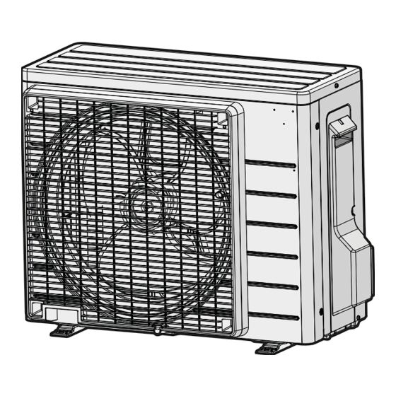
Daikin R32 Split Series インストレーション・マニュアル
[Method of mounting conduit]
• A protection plate is fixed for protection from the high-voltage section.
1) Dismount the stop valve cover by removing the screw.
2) Dismount the protection plate by removing the 3 screws.
3) Dismount the conduit mounting cover by removing the 3 screws.
4) Pass wires through the conduit and secure them with a lock nut.
5) After completing the work, reattach the stop valve cover, the protection plate, and the conduit mounting cover to its
original position.
1
2
3
L
1
L
2
Conduit
mounting cover
Conduit
Lock nut
Facility Setting
(cooling at low outdoor temperature)
WARNING
• Make sure to turn the power OFF before removing the electrical wiring box cover.
CAUTION
• If the outdoor unit is installed where the heat exchanger of the unit is exposed to direct wind, provide a windbreak wall.
• Intermittent noises may be produced by the indoor unit due to the outdoor fan turning on and off when using facility settings.
• Do not place humidifiers or other items which might raise the humidity in rooms where facility settings are being used.
A humidifier might cause dew condensation from the indoor unit outlet vent.
• Cutting jumper 4 (J4) sets the indoor fan tap to the highest position.
Notify the user about this.
This function is designed for facilities such as equipment or computer rooms. It is never to be used in a
residence or office where people occupy the space.
„ Cutting jumper 4 (J4) on the circuit board will extend the operation range to 14°F (–10°C). Installing an air direction adjustment
grille (sold separately) will further extend the operation range to –4°F (–20°C). In these cases, the unit will stop operating if the
outdoor temperature falls below –4°F (–20°C), restarting once the temperature rises above this level.
1) Remove the top plate of the outdoor unit. (4 screws)
2) Remove the electrical wiring box cover.
3) Cut the jumper (J4) of the PCB inside.
English
Power supply
terminal block
GR
Shape wires so that the
protection plate and
conduit mounting plate fit
securely.
Protection plate
1
2
3
Conduit
mounting
cover
Screws
Screws
10