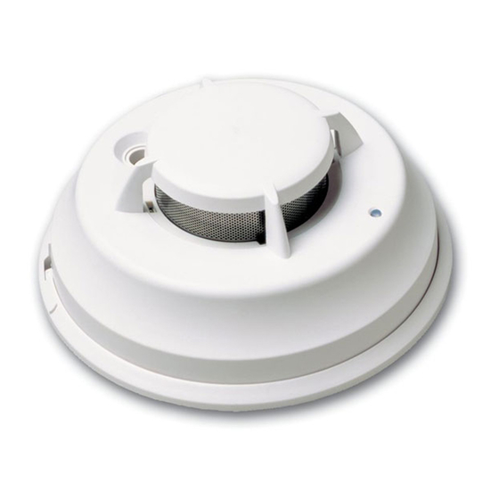
煙警報器 DSC FSA-210 SeriesのPDF 設置および操作説明書をオンラインで閲覧またはダウンロードできます。DSC FSA-210 Series 4 ページ。 2-wire photoelectric smoke detector

Read this instruction sheet thoroughly before installation and use of the
FSA-210 2-Wire Smoke Detector. This instruction sheet is intended to be used
with the Installation Manual of the alarm control panel. All the instructions spec-
ified within that manual must be observed.
Piezo Siren
Introduction
The FSA-210 is a 2-wire photoelectric smoke detector with the
following available options: fixed temperature
heat detector, internal piezoelectric alarm, auxiliary form C
relay, and/or remote LED output. Three versions are available:
US version (UL), Canadian version (ULC) and an International
version (EU).
NOTE: Heat detection based on rate of rise has not been
investigated by UL/ULC.
Operation
Approximately every 7 to 8 seconds the unit tests for a smoke
or heat alarm condition. During this sequence the unit also
performs self diagnostics, and checks for faults. During normal
operation the LED will flash every 50 seconds and the siren will
not sound.
Smoke Alarm
The smoke detector has a nominal fixed alarm sensitivity (refer
to the Specifications on the last page) and it will go into alarm
Installer Instructions
1. Smoke Detector Placement
On smooth ceilings, detectors
may be spaced 9.1M (30 feet)
apart as a guide. Other spacing
may be required depending on
ceiling height, air movement, the
presence of joists, uninsulated
ceilings, etc. Consult National Fire
Alarm Code NFPA 72, Chapter 11
CAN/ULC-S553-02
or
appropriate national standards for
installation recommendations.
29006015R007
FSA-210 Series Smoke Detector
Installation and Operating Instructions
LED / Test Button
Place magnet here
Alignment Marks
and rate of rise
other
when the signal level exceeds the 'alarm' threshold and send
the alarm signal to the control panel. During an alarm the LED
will flash once per second and the siren will sound the evacua-
tion temporal pattern (UL, EU) or continuous beeps (ULC).
Remote Alarm - Interconnection
Multiple detectors (with sirens) can be connected using the
PRM-2W Polarity Reversal Module. When a fire alarm occurs,
the panel will signal the PRM-2W to reverse the polarity of the
2-wire loop. This will activate the sirens of all units connected
on the loop. Refer to the PRM-2W/4W Installation Instructions
for installation details.
Smoke - Drift Compensation
The detector automatically compensates for long-term envi-
ronmentally induced changes to maintain a constant smoke
sensitivity. When the drift compensation has reached its high
or low limit of adjustment, the detector will go into the trou-
ble state.
Heat Alarm
The heat detector will go into alarm when the heat signal level
exceeds the heat alarm threshold (135ºF/57ºC); and send the
alarm signal to the control panel. The detector will also go into
heat alarm if there is a rapid increase in the temperature over a
short period of time. During an alarm the LED will flash once
per second and the siren will sound the evacuation temporal
pattern (UL, EU) or continuous beeps (ULC).
Alarm Indications
Condition
LED
Normal / Sensitivity
in Production Range Flash 1/50s
Alarm Smoke/Heat
Flash 1/1s
Alarm Restore
Flash 1/1s
Remote Alarm
Flash 1/50s
Low Power Trouble
OFF
Other
OFF
Fault / Trouble
Test Switch - Failed
OFF
Test Switch - Pass
Flash 1/1s
Do NOT locate smoke detectors at the top of peaked or
gabled ceilings; the dead air space in these locations may pre-
vent the unit from detecting smoke. Avoid areas with turbulent
air flow, (near doors, fans or windows). Rapid air movement
around the detector may prevent smoke from entering the
unit. Do NOT locate detectors in areas of high humidity.
Do NOT locate detectors in areas where the temperature rises
above 38ºC (100ºF) or falls below 5ºC (41ºF).
Install smoke detectors in accordance with NFPA 72,
Ch. 11: "Smoke detectors shall be installed outside of each
sleeping area in the immediate vicinity of the bedrooms and
on each additional story of the family living unit, including
basements and excluding crawl spaces and unfinished attics.
Alarm
siren
Relay
Current
OFF
Deactivated
Temporal or
Activated
Steady
Temporal or
Activated
Steady
Temporal or
Deactivated
Steady
OFF
Deactivated
CHIRP 1/50s Deactivated
CHIRP 1/50s Deactivated
Temporal or
Activated
Steady
No
Yes
Yes
No
No
No
No
Yes
