- ページ 3
マイク DSPPA MAG6588のPDF クイック・スタート・マニュアルをオンラインで閲覧またはダウンロードできます。DSPPA MAG6588 3 ページ。 Network paging station

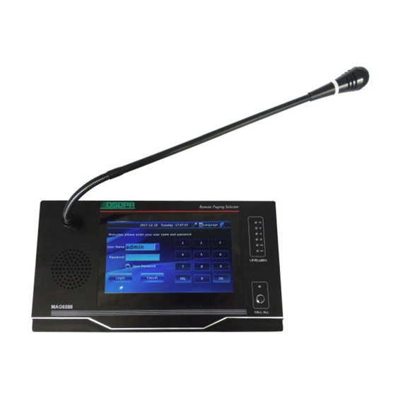
1. Microphone head
Please do NOT hit the microphone head when the
equipment is in use.
2. Microphone On/Off indicating ring
Indicating LED:
When the microphone is on, the indicating
light will be on.
The microphone On/Off indicating light will
be turned on simultaneously when calling
zones.
3. Microphone Rod
Users can adjust the microphone angel flexibly.
4. Microphone base
5-pin XLR:
Feet 1 for tube microphone red light;
Feet 2 for tube microphone blue light;
Feet 3 for voice signal input;
Feet 4 for grounding of signal input;
Feet 5 for MIC indicator power supply.
PHONES
LINE IN
VOL
1. On/Off Switch
When the button at "一" position is pressed to turn
on the power, while when the button at " 一 "
position is popped up to turn off the power.
2. Power Supply Interface
It provides working power supply for the machine.
3. Network Interface
It is used to connect to network switches.
4. USB Interface
The USB flash drive is inserted into the interface to
provide program source to the built-in MP3 player,
so as to realize the song push function of the USB
flash drive.
5. Data Exchange Interface
It is the RS232 analog paging interface and is
reserved for extension by intelligent systems.
6. Data Exchange Interface
/
警告
请勿打开,以免触电
POWER
广州市迪士普音响科技有限公司
DC/+14V
LAN
Guangzhou DSPPA Audio Co.,Ltd.
1
2
3
www.dsppatech.com
5. Microphone plug
Feet 5 corresponding respectively to the five feet on
the base.
6. Monitoring speaker
It is used to output the voices received.
7. Output level indicating LED
More indicating LEDs will be on as the output
volume increases.
8. LCD true color display
It is used to display the operating status and
operation interface of the paging station; the touch
screen is for selecting options.
9. Microphone On/Off indicating LED
The indicating LED is on when the user presses
"CALL ALL" button to activate all zones. It will also
be on when any terminal is called.
10. Paging button
It is used to realize paging function for all zones
CAUTION
COM
TX
RX
COM
A
B OUT+
OUT-
RISK OF
ELECTRIC SHOCK
DO NOT OPEN
USB
RS232
RS485
HEADPHONE
4
5
6
7
RS485 analog paging interface and is reserved for
extension by intelligent systems.
7. Monitoring Headphone Jack
It is for use of local monitoring and the volume is
adjustable.
8. Network Audio Output
9. Line Audio Output Interface
It is used to connect the system to amplification
equipment.
10. Line Audio Input Interface
It is used to connect to players, such as a DVD
player or a tuner.
11. Monitoring Volume Adjusting Knob
It is used to adjust the volume output to monitoring
headphone. Turn the knob clockwise to increase
the volume and anticlockwise to reduce the volume.
The specifications will be subject to change without prior notice.
Copyright © Guangzhou DSPPA Audio Co.,Ltd All rights served.
PHONES
NET AUDIO
AUX OUT
LINE IN
VOL
8
9
10
11
