- ページ 5
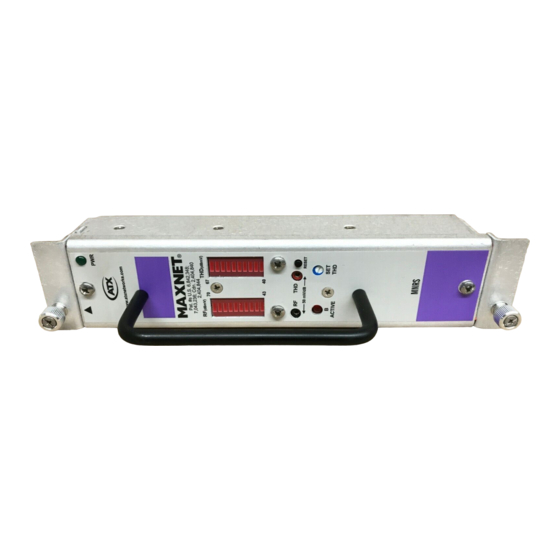
コントロールユニット ATX MAXNET MNRSのPDF インストレーション&オペレーションマニュアルをオンラインで閲覧またはダウンロードできます。ATX MAXNET MNRS 14 ページ。 Redundant rf detector/switch module

OPERATION
1.
Operation
1.1.
Operational Details
The MAXNET MNRS RF switch provides redundancy in an RF amplifier system. When a failure occurs in the primary
amplifier (A) control transfers to a secondary backup amplifier (B). The failure of the amplifier is determined by measuring
the total composite RF power at the output of the primary (A) amplifier and comparing it to the set RF power threshold level.
If total composite RF power drops below the threshold level the MNRS transfers to the secondary (B) amplifier to maintain
normal operation. The switch remains in the B position until the primary (A) amplifier is repaired or replaced and the MNRS
is reset.
1.2.
Operational Summary
Installation into MAXNET
Install the MNRS into the MAXNET chassis by following the MAXNET RF Detector/Switch and Amplifier Installation sheet
provided with the unit.
Threshold Setting:
Front panel SET THD potentiometer.
Reset:
Front panel momentary push button – press to set primary (A) amplifier active.
Switch Status:
Front panel LED and Relay Contact on rear terminal block.
Power Failure:
Switch Transfers to B position when MNRS power is lost.
NOTE: This device is not intended for exact power measurements.
It is intended to make a nominal total composite RF power measurement and compare it to a user defined threshold
in order to determine the necessary switch status
MAXNET
– MNRS Redundant RF Detector/Switch Module – Installation & Operation Manual
®
ATX Confidential & Proprietary
FROM A
RF OUT
FROM B
TO A
RF IN
TO B
Figure #1: MNRS Functional Schematic Diagram
®
Chassis:
RF
DETECTOR
CONTROL
LOGIC
RF
THD
SET THD
(Schematic indicates operation
RF (dBmV) THD (dBmV)
when device is not powered)
CHAPTER 1: OPERATION
RLY NO
RLY COM
1-1
