- ページ 3
アクセサリー Comunello LD100 100のPDF インストールとユーザーマニュアルをオンラインで閲覧またはダウンロードできます。Comunello LD100 100 4 ページ。 Inductive sensor
5 DIAGNOSTICS
SYMPTOM
POSSIBLE CAUSE
The POWER LED is
No power supply voltage
not on.
on the input.
The DETECT LED flashes
There may be a poor
erratically.
connection in the loop or
loop feeder.
The detector may be
experiencing crosstalk vith
the loop of an adjacent
detector.
The DETECT LED
Faulty loop or loop feeder
randomly stays on.
wiring.
Movement of the loop in
the ground.
The LOOP FAULT LED is
The loop inductance is to
flashing.
small or the loop is short
circuit.
The LOOP FAULT LED is
The loop inductance is to
permanently illuminated.
large or the loop is open
circuit.
6
WIRING DIAGRAM
5
10
PRESENCE RELAY
OUTPUT
6
TWISTED
LOOP
CABLE
LD100 220VAC / LD101 110VAC
LD102 12-24VAC/DC
EARTH
7
RELAY FUNCTIONALITY
VEHICLE
RELAYS
PRESENT
N/O
CLOSED
PRESENCE
RELAY
N/C
OPEN
PULSE
N/O
CLOSED
PULSE
RELAY
PULSE
N/C
OPEN
8
INSTALLATION GUIDE
• The detector should be installed in a waterproof housing as close to the
loop as possible.
• The loop and feeder should be made from insulated copper wire with a
minimum cross-sectional area of 1.5mm2. The feeder should be twisted
with at least 20 turns per metre. Joints in the wire are not recommended
6
COMUNELLO ®Copyright 2019 - All rights reserved
SOLUTION
Check that the power
supply is correctly wired
to the detector. (PINS 1
and 2)
Check all wiring. Tighten
screw terminals.
Check for broken wires.
Try changing frequencies
using the frequency
switch. Put the detector
with the larger loop onto
low frequency and the
detector with the smaller
loop onto high frequency.
Check the wiring. Tighten
screw terminals. Check
for pinched or bent wires.
Is the feeder wire twisted?
Check for cracks in the
road surface near the
loop.
Check that there is no
short circuit on the loop
feeder wiring or the loop.
If there is no short circuit
then the inductance is to
small and more turns of
wire should be added to
the loop.
Check that there is
electrical continuity on the
loop. This can be done
using a multimeter on the
ohms range (< 5 Ω). If
the loop inductance is to
large then try reducing the
number of turns.
3
11
PULSE RELAY
OUTPUT
4
7
LOOP INPUT
8
1
2
POWER INPUT
9
LOOP
NO
NO VEHICLE
FAULTY
POWER
OPEN
CLOSED
CLOSED
CLOSED
OPEN
OPEN
OPEN
OPEN
OPEN
CLOSED
CLOSED
CLOSED
and must be soldered and made waterproof. Faulty joints could lead to
incorrect operation of the detector. Feeders which may pick up electrical
noise should use screened cable, with the screen earthed at the detector.
• The loop should be either square or rectangular in shape with a minimum
distance of 1 metre between opposite sides. Normally 3 turns of wire
are used in the loop. Large loops with a circumference of greater than
10 metres should use 2 turns while small loops with a circumference of
less than 6 metres should use 4 turns. When two loops are used in close
proximity to each other it is recommended that 3 turns are used in one and
4 turns in the other to prevent cross-talk.
• Cross-talk is a term used to describe the interference between two
adjacent loops. To avoid incorrect operation of the detector, the loops
should be at least 2 metres apart and on different frequency settings.
• For loop installation, slots should be cut in the road using a masonry
cutting tool. A 45o cut should be made across the corners to prevent
damage to the wire on the corners. The slot should be about 4mm wide
and 30mm to 50mm deep. Remember to extend the slot from one of the
corners to the road-side to accommodate the feeder.
• Best results are obtained when a single length of wire is used with no
joints. This may be achieved by running the wire from the detector to the
loop, around the loop for 3 turns and then back to the detector.
The feeder portion of the wire is then twisted. Remember that twisting the
feeder will shorten its length, so ensure a long enough feeder wire is used.
• After the loop and feeder wires have been placed in the slot, the slot is
filled with an epoxy compound or bitumen filler.
TRAFFIC
DIRECTION
300mm
300mm
ROAD
1M
EDGE
O
45
CROSSCUT
FEEDER
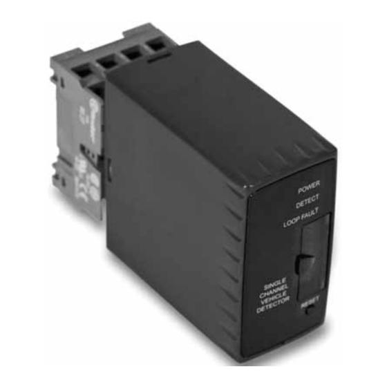
9 INDUCTIVE SENSOR - DETECTOR OF
METAL MASSES
The AC - 240 is a single channel inductive loop detector. The use of
microprocessor and surface mount technology enables a large number of
functions to be incorporated into a small package. The AC - 240 is compatible
with most single channel detectors on the market and is easy to set-up and
install.
Typical applications are: parking area and access control environments with
safety loops, arming loops and entry or exit loops.
Standard features of the detector are:
DIP-SWITCH no. 10:Reset Switch.
Pressing the reset switch enables the detector to be manually reset during
commissioning and testing. This results in the detector re-tuning the sensing
loop and becoming ready for vehicle detection.
DIP-SWITCESH no. 7-8-9. Switches of selectable Sensitivity.
Eight sensitivity settings are available on the switches to allow flexibility in
configuration.
SENSIBILITY
DIP 9
DIP 8
DIP 7
0,02 %
OFF
OFF
OFF
0,01 %
ON
OFF
OFF
0,05 %
OFF
ON
OFF
0,1 %
ON
ON
OFF
DIP-SWITCH n° 6: Switch selectable Frequency.
The frequency of the loop is determined by the inductance of the loop and
the frequency switch setting. If the frequency switch is on, the frequency is
reduced. It may be necessary to change the frequency to prevent cross-talk
between adjacent loops.
DIP-SWITCH no. 5: Sensitivity Boost.
This feature sets the undetect level to maximum sensitivity and is used to
prevent loss of detection of high-bed vehicles.
ROAD SURFACE
SLOT
30-50 mm
SEALANT
WIRES
4mm
SENSIBILITY
DIP 9
DIP 8
DIP 7
0,2 %
OFF
OFF
ON
0,5 %
ON
OFF
ON
1 %
OFF
ON
ON
2 %
ON
ON
ON