- ページ 2
ネットワーク・ルーター 3onedata IES3020-4GS-PのPDF ユーザーマニュアルをオンラインで閲覧またはダウンロードできます。3onedata IES3020-4GS-P 4 ページ。 Ies3020-4gs series industrial ethernet switch
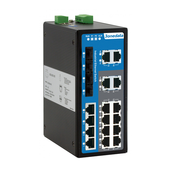
8.
Relay alarm LED
9.
Power indicator
10. Gigabit SFP port
11. 100Base-FX fiber port
12. Link/ACT LEDs
13. 10Base-T /100Base-TX Ethernet port
【Power supply input】
The switch top panel provided 4 bit power supply input
terminal block, support DC input. DC power supply input
supported redundancy function, provided PWR1 and PWR2
power input, can use for single, and can connect 2
separately power supply system, use 1 pair terminal block
connect the device at the same time. If one of the power
systems broke, the device can work un-interruptible. Built-in
overcorrect protection, Reverse connection protection.
Voltage input range is 12~48VDC (terminal block defined
as: V1-, V1+, V2-, V2+).
【Dimension】
The series of products are the same size, and the number of
the Ethernet interface is different. Unit (mm)
【DIP Switch】
Top panel provided 4 bits DIP switch to do function configure
(ON to enable effective), 1 keep for future function. 2 is
double power alarm. 3 is flow control. 4 is broadcast storm
suppress features. Please power off and power on when you
change the status of DIP switch.
【Relay connection】
Relay access terminals in the top panel of the device.
Between the two terminal relay, as a closed circuit state in
normal non alarm state, when there is any alarm information
to the open state. The two terminal block connector are used
to detect power failure. The two wires attached to the Fault
contacts form an open circuit when the device has lost
power supply from one of the DC power inputs is failure.
【Console port】
The switch provided 1pcs procedure test port based in serial
port. It adopts RJ45 interface, located in top panel, can
configure related command through RJ45 to DB9 female
cable.
【Communication connector】
10/100BaseT(X) Ethernet port
The pinout define of RJ45 port display as below, connect by
UTP or STP. The connect distance is no more than 100m.
100Mbps is used 120Ω of UTP 5, 10Mbps is used 120Ω of
- 2 -
UTP 3, 4, 5.
RJ45 port support automatic MDI/MDI-X operation. can
connect the PC, Server, Converter and HUB .Pin 1,2,3,6
Corresponding connection in MDI. 1→3, 2→6, 3→1, 6→2
are used as cross wiring in the MDI-X port of Converter and
HUB. 10Base-T/100Base-TX are used in MDI/MDI-X, the
define of Pin in the table as below.
NO.
MDI signal
1
TX+
2
TX-
1
8
3
RX+
6
RX-
4, 5, 7, 8
—
Note:"TX±"Transmit Data±,"RX±"Receive Data±,"—" Not use.
10/100Base-T(X) MDI (straight-through cable)
10/100Base-T(X) MDI-X (Cross over cable)
MDI/MDI-X auto connection makes switch easy to use for
customers without considering the type of network cable.
100Base-FX Fiber port
100Base-FX full-duplex SM or MM port, SC/ST/FC type .The
fiber port must be used in pair, TX (transmit) port connect
MDI-X signal
RX+
RX-
TX+
TX-
—