- ページ 3
ネットワーク・ルーター 3onedata IES6116-2F-PのPDF クイック・インストール・マニュアルをオンラインで閲覧またはダウンロードできます。3onedata IES6116-2F-P 4 ページ。 Managed industrial ethernet switch
3onedata IES6116-2F-P にも: ユーザーマニュアル (5 ページ)
pins 7.62mm pitch power input terminal blocks. The definitions
of terminal blocks as follows: N/-, PG, L/+.
Power supply range: 100~240VAC/DC.
【Relay Connection】
Relay terminal blocks are a pair of normally
open contacts in the alarm relay of the device.
They are open circuit in the status of normal no
alarm, and closed when any warning message occurs. For
example: they are closed and send out alarm when power off.
The product supports 1 relay warning message output, and
warning messages output of the DC power supply or network
abnormal alarm output. It can be connected to alarm indicator,
alarm buzzer, or other switching value collecting devices for
timely warning operating staffs when the warning message
occurs.
【DIP Switch Settings】
The product provides 4 pins DIP switch for
function settings, where "ON" is the enable valid
terminal.
Please
power
changing the DIP switch status.
DIP switch definitions as follows:
DIP
Definition
Operation
1.
Reserved
-
2.
Restore
Set the DIP switch to ON, the
factory
device will automatically
defaults
restore factory defaults, and
then turn off the DIP switch.
3.
Upgrade
Set the DIP switch to ON for
upgrading the device, and then
turn it off.
4.
Reserved
-
【Console Port Connection】
The device provides 1 procedure debugging port based on
serial port, and can manage the CLI command line of the
device after connected to PC. The interface adopts RJ45 port,
the RJ45 pins definition as follows:
Pin No.
2
3
Definition
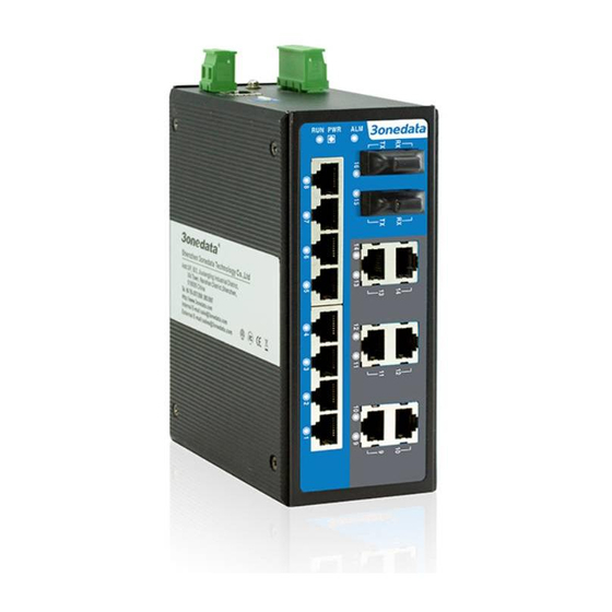
【Checking LED Indicator】
The function of each LED is described in the table as below:
LED
Status
ON
PWR/
P1/P2
OFF
ON
ALM
OFF
ON
RUN
OFF
Blinking
ON
Link/
ACT
Blinking
(1-16)
on
again
before
OFF
【Logging in to WEB Interface】
This device supports WEB management and configuration.
Computer can access the device via Ethernet interface. The
way of logging in to device's configuration interface via IE
browser is shown as below:
Step 1
Configure the IP addresses of computer and the
device to the same network segment, and the
network between them can be mutually accessed.
Step 2
Enter device's IP address in the address bar of the
computer browser.
Step 3
Enter device's username and password in the login
window as shown below.
5
TXD
RXD
GND
Description
Power supply is connected and running
normally
Power supply is disconnected and
running abnormally.
Power supply and port link alarm
Power supply and port link without
alarm
The device is powering on or
abnormal.
The device is powered off or abnormal.
Blink once per second, the device is
running well.
Ethernet port connection is active.
Data transmitted
Ethernet port connection is inactive.
Click "OK" button to login to the WEB interface of
Step 4
the device.
Note:
The default IP address of the device is "192.168.1.254".
The default username and password of the device is
"admin".
If the username or password is lost, user can restore it to
factory settings via device DIP switch or management
software; all modified configurations will be cleared
after restoring to factory settings, so please backup
configuration file in advance.
Please refer to user manual for specific configuration
method of logging in to WEB interface and other
configurations about network management function.
【Specification】
Panel
10/100Base-T(X) self-adapting
RJ45 port, full/half duplex
100M copper port
self-adaption or specified
operating mode, support
MDI/MDI-X self-adaption
100Base-FX, optional SC/ST/FC
100M fiber port
interface