- ページ 4
エアコン Addison BのPDF インストレーション、オペレーション、メンテナンスマニュアルをオンラインで閲覧またはダウンロードできます。Addison B 19 ページ。 High efficiency packaged air conditioning systems

GENERAL DESCRIPTION
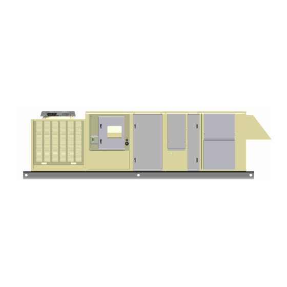
The model DC Series B packaged cooling and heating
unit is designed to cool a conditioned space with
mechanical
refrigeration,
conservation wheel or a combination of these systems.
During the heating mode supply air may be heated by
indirect fired gas, electric strip, steam or hot water. The
cabinet design provides space for a number of options,
including 100% outside air applications and the use of
desiccant wheels. Most of these options will be covered in
this manual; for those of a more custom nature, consult the
ADDISON Application Engineering Department.
Models DC units are designed for rooftop curb, slab
mounted or installed on post and rail applications with field
convertible vertical or left and right horizontal return and
supply air duct connections.
Unpacking, Inspection
When received, the unit should be checked for damage
that might have occurred in transit. If damage is found, it
should be noted on the carrier's Freight Bill. Request for
inspection by carrier's agent should be made in writing at
once.
Design Certification
All units are certified by Electrical Testing Laboratories
(E.T.L.) under ANSI/UL 1995. The gas furnace designs are
certified by E.T.L. under ANSI Z83.9 (latest edition) for use
with natural or propane (L.P.) gas as specified when
ordering unit.
INSTALLATION
Unit Location, Clearances
An intake louver protects the service end and clearance at
this point should be maintained. A 36" clearance must be
allowed for access to the compressor and electrical panel.
A 24" clearance must be maintained for the air inlet to the
condenser coil(s). Do not locate the unit under an
overhang that will short circuit hot air to the coil intakes.
When installed at ground level, the unit should be mounted
on a level concrete slab which should extend at least 2"
beyond the unit on all sides. The top of the slab should be
2" above the ground level.
The depth of the slab below the ground level and its
structural design is governed by the type of soil and
climatic conditions. The slab must not be in contact with
any part of the building wall or foundation. The space
between the slab and building wall prevents the possibility
of transmitting vibration to the building.
The dimensions of the slab or roof mount should be
checked and verified before the equipment arrives. Unit
supports,
roof
opening,
requirements, and electric locations are important to a
good installation.
When installing the equipment on top of a building, the
following should be considered:
Structural members supporting the unit must be sufficiently
strong for the weight of the unit and mounting rails.
Transmission of sound into the building is sometimes a
problem when the structure is not strong enough.
Locate the unit as near as possible to the center of the
area to be environmentally controlled. Sufficient clearance
chilled
water,
energy
roof
curb
flashing,
drain
Codes and Ordinances
These units must be installed in accordance with the
standard of the National Fire Protection Association or the
National Fuel Gas Code ANSI Z83.9 (latest edition). The
National Fuel Gas Code is available from the American
Gas Association, 1515 Wilson Boulevard, Arlington, VA
22209. NFPA Publications are available from the National
Fire Protection Association, Batterymarch Park, Quincy,
MA 02269. Local authorities having jurisdiction should be
consulted before installations are made to verify local
codes and installation procedures.
All field wiring to the unit must be done in accordance with
these instructions, the National Electric Code (ANSI/NFPA
70-1981) in the United States and all local codes and
ordinances.
Clearances from the heater and vent to construction or
material in storage must conform with the National Fuel
Gas Code ANSI Z83.9 (latest edition), pertaining to gas-
burning devices, and such material must not attain a
temperature over 160°F by continued operation of the
heater.
Installation should be done by a qualified agency in
accordance with the instructions in this manual and in
compliance with all codes and requirements of authorities
having jurisdiction.
must be available for service, edge of roof, other units, or
hazards.
The condenser air inlet and discharge air must be
unobstructed by overhang, walls, or other equipment.
Avoid locations next to exhaust fans or flues.
Select a location where external water drainage cannot
collect around the unit.
Locate the unit so roof runoff water does not pour directly
on the unit. Provide gutter or other shielding at roof level.
Where snowfall is anticipated, mount the unit above the
maximum snow depth for the area.
Curb Installation, Protrusions
Proper installation for the DC series requires that the roof
mounting, field assembled curb be firmly and permanently
attached to the roof structure. Check for adequate
fastening method prior to setting rooftop unit on curb.
Inspect curb to insure that none of the utility services
(electric, gas, drain lines) routed through the curb protrude
above the curb. Duct connections will normally be made
after unit is set on curb. If duct is prefabricated and
installed within the curb prior to setting unit, insure that
ductwork does not protrude above curb.
CAUTION: DO NOT ATTEMPT TO SET UNIT ON CURB
IF PROTRUSIONS EXIST.
CAUTION: Units may look identical but have significant
internal differences.
Check specific unit location carefully (referring to plans if
necessary) prior to setting unit.
3
