- ページ 8
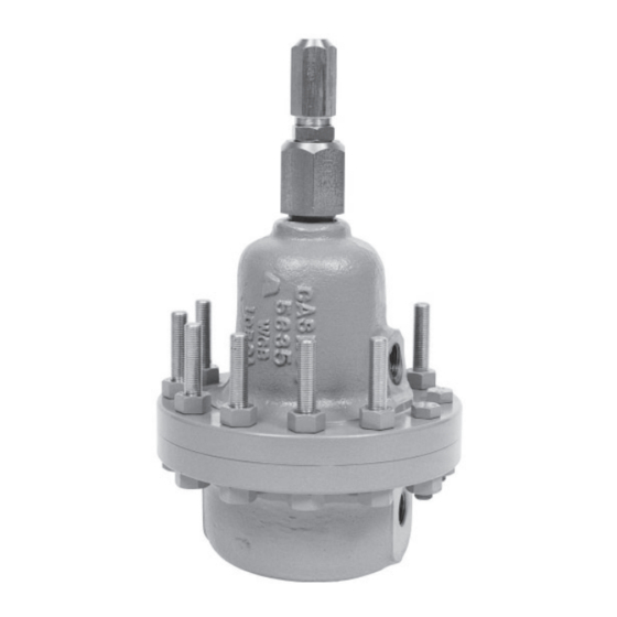
コントローラー cashco 123-1+6+SのPDF インストレーション、オペレーション&メンテナンスマニュアルをオンラインで閲覧またはダウンロードできます。cashco 123-1+6+S 10 ページ。 Differential back pressure/relief regulator

9
2
19
18
6
27
*
*
*
41
42
8
*
3
*
1
21
34
*
12.2
12.1
12
*
.......
Item No.
1 ..................................................Body
2 ................................Spring Chamber
3 .........................................Diaphragm
6 ..........................................Piston Nut
7 ..................... Cap Screw (Hex Head)
8 ...........................................Nut (Hex)
9 ............................................Lock Nut
10 .................. Name Plate (not shown)
12 ....................Cylinder Sub-Assembly
12.1 ......................................Cylinder
12.2 ............................................Seat
14 ............................................... Piston
17 ............................... Adjusting Screw
18 ................................... Range Spring
19 ................................... Spring Button
Cashco, Inc.
P.O. Box 6
Ellsworth, KS 67439-0006
PH (785) 472-4461
Fax. # (785) 472-3539
www.cashco.com
email: [email protected]
Printed in U.S.A. IOM-123-1+6+S
Figure 5: Model 123-1+6+S
(Non-NACE Construction)
Description
Cashco do Brasil, Ltda.
Cashco GmbH
Al.Venus, 340
Handwerkerstrasse 15
Indaiatuba - Sao Paulo, Brazil
15366 Hoppegarten, Germany
PH +55 11 99677 7177
PH +49 3342 30968 0
Fax. No. +49 3342 30968 29
Fax. No.
www.cashco.com
www.cashco.com
email: [email protected]
email: [email protected]
22
17
28
*
29
*
Seal Welded per ASME
BPVC Code Section IX
1/2" (DN15) NPT
Loading Connection.
20
*
30
7
32
*
Opt-33 Third Body
Con nec tion
31
*
35
14
*
Seal welded per ASME BPVC
Code Section IX & API 614
(Both Nipples)
Re pair
Parts
Item No.
20 ................................. Pressure Plate
21 .................................... Pusher Plate
22 ..................................... Closing Cap
*
24 .......................... Diaphragm Covers
*
27 ................................Sealing Washer
*
28 .....................................Backup Ring
29 ........................................Quad Ring
30 .....................Cap Screw (Hex head)
31 ...................... Pressure Plate O-ring
*
32 ................ Diaphragm Flange O-ring
33 ..............................Cylinder Bushing
*
34 ......................... Pusher Plate O-ring
35 ..........................................Pipe Plug
41 ..................................................Stud
42 ..................................................Stud
1
Figure 7: Orientation of
Ring Seals (28,29)
*
Figure 6: Cylinder Bushing (33)
(Used on 1-1/2" (DN40)
reduced orifi ce ONLY)
.......
Description
(Used on 1-1/2" Reduced Orifi ce only)
NACE Construction only (not shown).
17
28
*
29
*
33
Re pair
Parts
*
1
*
*
*
*
*
*
*
*
*
