- ページ 4
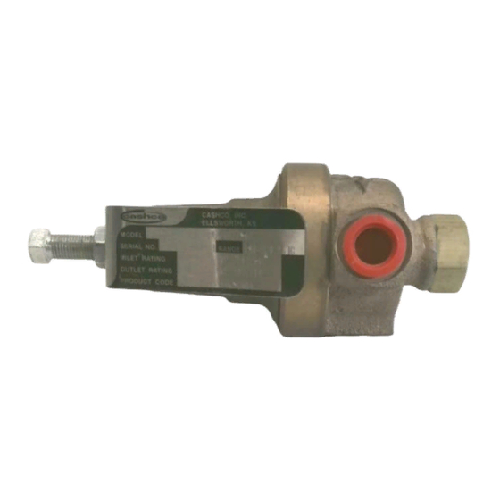
コントローラー cashco 3381のPDF インストレーション、オペレーション&メンテナンスマニュアルをオンラインで閲覧またはダウンロードできます。cashco 3381 10 ページ。 Pressure reducing regulators
cashco 3381 にも: インストレーション、オペレーション&メンテナンスマニュアル (8 ページ)

stan dard #S-1134. For regulators originally
sup plied as "cleaned for Phar ma ceu ti cal
and Food applications" Options 4381-37
and 4381-37S, maintenance must include a
level of clean li ness equal to Cashco cleaning
stan dard #S-1576. Con tact fac to ry for details.
10. Reassemble diaphragm subassembly by
plac ing pusher plate seal (15) over thread ed
post of pusher plate (4), placing diaphragm(s)
(13) and pressure plate (3) over the threaded
post.
Assure the pressure plate (3) is
placed with curved outer rim down next to
the diaphragm (13) surface. Place a thread
sealant compound on the threads of the
push er plate post (4) prior to tightening the
pusher plate nut (10) to the fol low ing torque
values:
Sizes
Diaphragm
ALL
Composition
11. For metal diaphragm(s) (13), place dia phragm
gas ket (14) into body (1) re cess (none
re quired for com po si tion di a phragm). Set
di a phragm sub as sem bly into the body.
12. Place the range spring (17) over the pusher
plate nut (10) of the diaphragm subassembly.
13. Place multipurpose, high temperature grease
into de pres sion of spring button (5) where
ad just ing screw (8) makes contact. Set spring
but ton (5) onto range spring (17); en sure
spring button (5) is laying flat on top of spring.
14. Rotate the spring chamber (2) CW by hand
into the threaded portion of the body (1)
ensuring not to cross thread. Continue
ro tat ing CW into the body and tighten
approximately 1/4 turn past initial contact with
the diaphragm. Use caution when tightening
the spring chamber, contact with the wrench
on the vent hole boss may damage it.
15. Reinstall ad just ing screw (8) with locknut (11)
into the spring chamber (2).
16. Pressurize with air and spray liquid leak
de tec tor to test around body (1) and spring
cham ber (2) for leakage. En sure that an outlet
pressure is main tained during this leak test
of at least mid-range spring level; i.e. 20-80
psig (1.4-5.5 Barg) range spring, 50 psig
(3.4 Barg) test pres sure min i mum.
C. Diaphragm Replacement - Model 4381:
1. Procedures are the same as Model 3381.
4
Torque
In-lbs (N-m)
Metal
60
(6.8)
15
(1.7)
2. For SST body (1) and SST spring chamber
(2), use thread lubricant to minimize po ten tial
of seizing threads.
D. Special Instructions for Diaphragm Removal:
1. If the TFE coated diaphragm (13) is utilized on
the Model 4381, the TFE coating is the wetted
side of the diaphragm.
2. If the Option-2 is utilized, the ad just ing screw
(8) and locknut (11) are re placed with a
handwheel (18) and lock nut (11). With the
Option-22 panel mounting w/hand wheel,
the adjusting screw (8) and lock nut (11) are
re placed with a handwheel (18), lock nut (11)
and a panel mounting nut (19).
3. If the Option-1+6 is utilized with metal
diaphragms, there will be one diaphragm
gasket (14) on top of and one below the
diaphragm(s).
Option-1+6 contains single di a phragm con struc tion. In
the event of diaphragm fail ure, the process flu id will mix
with the load ing fluid. Please alert your rep re sen ta tive so
an al ter na tive product can be se lect ed.
E. Trim Replacement:
1.
Secure body (1) in a vise with the body cap
(6) oriented up and the spring chamber (2)
down wards.
To prevent damage to the body, use soft jaws when
securing body in a vise. Position body so that vise closes
over the inlet and the outlet connections.
2.
Loosen and remove body cap.
3.
Remove piston spring (7), and piston (16).
Note that the seat and piston guide are
in te gral parts of the body (1) cast ing. Inspect
integral seat and guide for ex ces sive wear,
espe cially at seat sur fac es. Replace if worn,
nicked or de pressed. If integral seat is nicked,
use seat lapping com pound to remove.
Valves equipped with Opt-4 Stabilizer will
have the u-cup stabilizer seal (30) removed
when the piston (16) is removed from body
(1). Remove stabilizer seal (30), if installed.
NOTE: When pis ton (16) assemblies are
used with com po si tion seats, Cashco, Inc.
does not recom mend at tempt ing to remove
the com po si tion seat. If composition seat is
damaged, re place entire piston assembly.
CAUTION
CAUTION
IOM-3381/4381
