- ページ 10
エンジン 3T-Components 3T-MOTORS 3T35のPDF 据付・取扱説明書をオンラインで閲覧またはダウンロードできます。3T-Components 3T-MOTORS 3T35 20 ページ。 Shutter / awning motors with mechanical limit switches, for shafts from 60/40 mm
INSTALLATION INSTRUCTIONS
On the opposite side of the motor, push the roller capsule out of the roller shutter shaft until it fits into the ball bearing inserted in the wall bearing.
•
Fix roller capsule to roller shutter shaft with self-tapping screw. Position the screw at a punched hole. This prevents the screw from slipping.
•
Roller capsule
Shutter motor wiring:
7
Connect the roller shutter motor and switch (or timer) to the mains.
•
The electrical connection of the roller shutter motor and control unit may only be carried out by qualified personnel.
•
If the drive should run in the opposite direction after installation, the motor's upstream and downstream leads (brown + black) must be turned.
•
Power grid
230 V / 50 Hz
1) brown / black = L1 / Phase
2) blue = N Neutral conductor
3) green/yellow = PE Protective conductor
The connection diagram of time switches differs from this circuit diagram!
Please refer to the corresponding manual for the connection diagram.
1 (L1)
2 (N)
3 (PE)
Wall bearing +
Ball bearing
1 (Up/Down)
2 (Up/Down)
3 (N)
4 (PE)
1) black = Departure or ascent
2) brown = Departure or ascent
3) blue = N Neutral conductor
4) green/yellow = PE Protective conductor
3T-MOTORS Tubular motors | Installation instructions
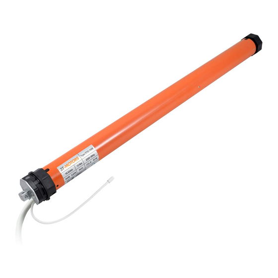
Shutter motor
230 V / 50 Hz
10