- ページ 15
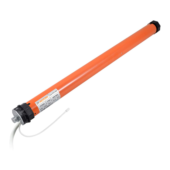
エンジン 3T-Components 3T-MOTORS 3T45のPDF 据付・取扱説明書をオンラインで閲覧またはダウンロードできます。3T-Components 3T-MOTORS 3T45 20 ページ。 Shutter / awning motors with mechanical limit switches, for shafts from 60/40 mm
INSTALLATION INSTRUCTIONS
Slide the side bearing with universal bearing onto the support tube & fasten.
•
Ensure that the motor square spigot is properly engaged in the universal bearing.
•
Secure the motor square spigot with the supplied cotter pin.
•
Attach the cover to the side bearing.
•
Install awning & release fuses.
•
3.9
Support tube
Side bearing &
Universal bearing
Awning motor wiring:
4
Connect the awning motor and switch (or timer) to the mains.
•
The electrical connection of the awning motor and control may only be carried out by qualified personnel.
•
If the drive should run in the opposite direction after installation, the motor's upstream and downstream leads (brown + black) must be turned.
•
Power grid
230 V / 50 Hz
1) brown / black = L1 / Phase
2) blue = N Neutral conductor
3) green/yellow = PE Protective conductor
>
fig. 3.11
>
fig. 3.12
3.10
1 (L1)
2 (N)
3 (PE)
>
fig. 3.9
>
fig. 3.10
3.11
Cotter pin
3.12
Cover
Awning motor
230 V / 50 Hz
1 (Up/Down)
2 (Up/Down)
3 (N)
4 (PE)
1) black = Departure or ascent
2) brown = Departure or ascent
3) blue = N Neutral conductor
4) green/yellow = PE Protective conductor
3T-MOTORS Tubular motors | Installation instructions
Side bearing
15