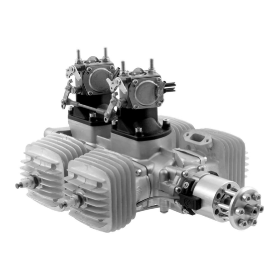
Ignition
Consideration needs to be given to the placement of the electronic ignition module. Avoid placing
the module in the path of hot air. Mount the ignition module using the four supplied rubber grommets
so as to create a 1/16" gap between the ignition module and the mounting surface. Without this
1/16" gap the ignition module can overheat. Important: If the electronic ignition overheats it will
malfunction (e.g., backfiring or shutting down).
Ignition details:
•
The red cable is positive (+)
•
The ignition timing has been set at our factory
•
When fitting a new ignition it is important to achieve the correct coordination of the sensor(s)
to the magnets
Canister mufflers
To prevent damage to the header(s) a flexible support bracket is required to mount the canister(s).
The location for this bracket should be at the canister's center of gravity. 3W canisters have a
reinforcement ring at this location.
We suggest creating two compartments in the front section of the fuselage by installing a horizontal
tray. Fuel tanks, batteries, and other equipment can be mounted on top of this tray; the canister(s)
being installed below it. Close off the lower compartment at its rear with an angled former. Locate
this former 1" behind the back of the canister(s). Next cut a hole in the bottom of the fuselage just
under the rear of the canister(s). In this way the air coming from the front of the model can flow
over the canister(s) and then be deflected by the angled former so as to exit through the hole in
112i B4 / QS Engine Manual
Refer to our special ignition description for further information
more infos: www.3w-modellmotoren.com
