- ページ 5
トランシーバー FreeBytes RadioKit-120のPDF 組立・取扱説明書をオンラインで閲覧またはダウンロードできます。FreeBytes RadioKit-120 11 ページ。 20μ cw ham radio transceiver kit

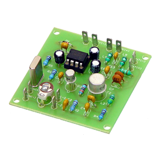
The board with the capacitors
placed.
Give special attention to soldering the electrolytic capacitors C9, C10 and C11
since they are polarized. The correct polarity is printed on the board. Finish the
construction by soldering IC1's 8 pin base, D1, T1, T2. Take care regarding the
placement of Transistors T1 and T2. Just follow the printed impressions on the
board. Solder the crystal, the provided input output pins and the 9V clip last.
Finished board
Please beware that there may be differences between the components
shown in the photos and the actual components provided with the kit
because of revision and production changes. See revision list at the
end of this document.
After finishing soldering check your work and make sure that there are no
accidental solder joints between different pads or conductors on the board.
Recheck the placement of all the components and make sure that everything is
