- ページ 13
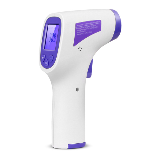
温度計 DANIU QY-EWQ-01のPDF マニュアルをオンラインで閲覧またはダウンロードできます。DANIU QY-EWQ-01 16 ページ。 Infrared forehead thermometer

- 1. Other Instructions‧‧‧‧‧‧‧‧‧‧‧‧‧‧‧‧‧‧‧‧‧‧‧‧‧‧‧‧‧‧‧‧‧‧‧‧‧‧‧‧‧‧‧‧‧‧‧‧‧‧‧‧‧‧‧‧‧‧‧‧‧‧‧‧‧1
- 2. Feature‧‧‧‧‧‧‧‧‧‧‧‧‧‧‧‧‧‧‧‧‧‧‧‧‧‧‧‧‧‧‧‧‧‧‧‧‧‧‧‧‧‧‧‧‧‧‧‧‧‧‧‧‧‧‧‧‧‧‧‧‧‧‧‧‧‧‧‧‧‧‧‧‧‧‧‧‧‧‧‧‧‧1
- 3. Description‧‧‧‧‧‧‧‧‧‧‧‧‧‧‧‧‧‧‧‧‧‧‧‧‧‧‧‧‧‧‧‧‧‧‧‧‧‧‧‧‧‧‧‧‧‧‧‧‧‧‧‧‧‧‧‧‧‧‧‧‧‧‧‧‧‧‧‧‧‧‧‧‧‧1
- 4. Operating Instructions‧‧‧‧‧‧‧‧‧‧‧‧‧‧‧‧‧‧‧‧‧‧‧‧‧‧‧‧‧‧‧‧‧‧‧‧‧‧‧‧‧‧‧‧‧‧‧‧‧‧‧‧‧‧‧‧‧‧4
- 5. Reference Temperature‧‧‧‧‧‧‧‧‧‧‧‧‧‧‧‧‧‧‧‧‧‧‧‧‧‧‧‧‧‧‧‧‧‧‧‧‧‧‧‧‧‧‧‧‧‧‧‧‧‧‧‧‧‧‧‧‧‧6
Recommended isolation distance between portable and mobile RF communication devices and infrared forehead
thermometers
Infrared forehead thermometers are intended for use in electromagnetic environments where radiated RF
disturbances are controlled. According to the maximum output power of the communication equipment. Purchasers
or users of infrared forehead thermometers can prevent electromagnetic interference by maintaining a minimum
distance between portable and mobile RF communication equipment (transmitters) and infrared forehead
thermometers as recommended below.
Transmitter's
rated
maximum output power
/ w
0.01
0.1
1
10
100
For the rated maximum output power of the transmitters not listed in the table above, the recommended isolation
distance d, in meters (m), can be determined using the formula in the corresponding transmitter frequency column,
where p is the emission provided by the transmitter manufacturer Machine maximum output power in watts (w).
Note 1: At 80MHz and 800MHz frequencies, the higher frequency range formula is used.
NOTE 2 These guidelines may not be suitable for all situations. Electromagnetic propagation is affected by
absorption and reflection from buildings, objects and people.
16.Symbol Description
Symbol graphics
Isolation distance for different frequencies of the transmitter / m
150kHz—80MHz
d=1.2
Not applicable
Not applicable
Not applicable
Not applicable
Not applicable
Meaning
Note, refer to the attached file
Low voltage alert
Trash
150kHz—80MHz
d=1.2
0.12
0.38
1.2
3.8
12
Symbol graphics
(
13 / 16
150kHz—80MHz
d=2.3
0.23
0.73
2.3
7.3
2.3
Meaning
Reference instructions
BF type application part
