- ページ 2
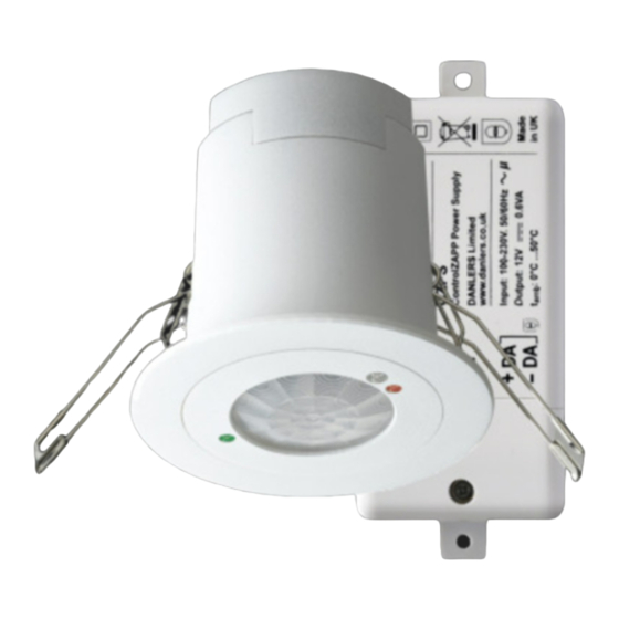
スイッチ DANLERS ControlZAPP CZ CEFL 10VDCのPDF インストレーション・ノートをオンラインで閲覧またはダウンロードできます。DANLERS ControlZAPP CZ CEFL 10VDC 2 ページ。 Ceiling flush mounted switch
DANLERS ControlZAPP CZ CEFL 10VDC にも: インストレーション・ノート (2 ページ)

Installation procedure
1. Please read these notes carefully before commencing work. In case of doubt
please consult a qualified electrician. Ensure wires and cables are securely held
within the connection terminals.
IMPORTANT: The CZ CEFL 10VDC Control Unit clock battery must be
engaged (ON) prior to installation by switching the RED dip switch (see
diagram D) to the DOWN position.
2. POSITIONING: The CZ CEFL 10VDC switch should be installed to achieve
correct coverage of the area, see diagram B. If the photocell override facility
(enabled via ControlZAPP app) is required, the switch must be located above
an area where daylight can give greater illumination than the artificial light. Avoid
locating this product where it is exposed to drafty conditions (exposed lobbies,
open ceiling voids or near fans) or near heat sources. To cover large areas PIRs
should be spaced in a 5 metre grid formation.
3. Disconnect the ControlZAPP device from the circuit before performing insulation
testing of the wiring circuit.
4. Do not connect on a circuit with large inductive loads, as induced spikes may
cause false triggering or damage the device.
5. CZ CEFL 10VDC must be connected to its ControlZAPP Power Supply via the
ControlZAPP communication cable provided, for wiring see diagram C.
NOTE: The use of non ControlZAPP connectors may damage the CZ CEFL
10VDC device and will invalidate the warranty.
Settings and calibration
NOTE: ALL settings are adjusted by ControlZAPP App as specified in the
ControlZAPP App User Guide (downloadable from the DANLERS website)
including: MODE settings, SCHEDULER settings and photocell settings and
intelligent photocell calibration procedure.
MODE settings include: Detect Movement (enable or disable), Sensitivity, Short
Visit Mode (with timer), Turn ON automatically (Presence detection or Absence
detection), Turn OFF timeout (from10sec to 23hrs 59min 59sec), Respond to
Daylight (enabled or disabled) the calibration process must be run for the intelligent
photocell to work. Delay before ON or Delay before OFF timers, Scene Recall (ON
or OFF).
SCHEDULER settings include:
DAY TYPES (defining times for each of the different Modes to occur).
WEEKLY SCHEDULE (defining which Day Types are assigned to different days of
the week).
EXCEPTIONS (defining exceptions to the schedule such as holidays).
VIEW ON CALENDAR (overview of schedule).
A: Mounting diagram
CEILING VOID
(At least 78mm deep)
75mm circular hole
cut for PIR switch
B: Detection diagram
Strong detection zone
i.e. person moving arm
or walking towards PIR
up to 5m
up to 7m
C: Wiring diagram
_
+
CZ CEFL 10VDC
L
SL
N
100 - 260VAC
50/60Hz
Optional
other load
N
D: Connector diagram
IMPORTANT
Red dip switch (MUST be
switched DOWN (towards lens)
SL
to engage clock battery ON)
L
L
Power Supply
N
+
-
For optimum coverage
recommended
mounting height: 2.4 to 5m
Secondary detection
zone i.e. person
walking perpendicular
to PIR
control lines
+
ballast
-
+
ballast
-
+
ballast
-
Control Unit
Telejack connector
